Chapter 2 Operating Principles
2-2.
Operation of Control Parts
2-47
CL-E700 series
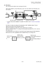
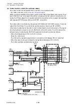
Abnormally high temperature detection:
To protect the cutter motor from being damaged, an abnormally high temperature detection
circuit is provided. If the temperature of the cutter motor exceeds a set temperature limit, the
LED on the operation panel blinks in red and the LCD displays “Error System Fail”, and the
printer goes off-line. To recover from the error status, turn OFF the printer once and then turn it
ON.
A reference voltage, i.e., an allowable temperature limit, is applied to pin 5 of the comparator
(U8B), while the sensor output voltage (TMPCUT) from the cutter motor temperature sensor is
applied to pin 6.
If the temperature of the cutter motor becomes higher than the set temperature limit, the cutter
motor temperature sensor output voltage exceeds the reference voltage at pin 5, and pin 7 of
U8B goes to “Low” level. At this time, pin K1 (nTMPERR) is “Low” and the FPGA detects an
abnormally high temperature.
In this abnormal state, the printer stops +24V DC (VMT) supply to the cutter. Also it stops +24V
DC supply to the “SA Head”, “SA PF Motor” and “SA Ribbon Motor F”.
Содержание CL-E700 Series
Страница 1: ...Technical Manual CL E700 series Thermal Transfer Printer...
Страница 5: ...Chapter 1 Specifications 1 1 CL E700 series CHAPTER 1 SPECIFICATIONS...
Страница 15: ...Chapter 2 Operating Principles 2 1 CL E700 series CHAPTER 2 OPERATING PRINCIPLES...
Страница 87: ...Chapter 3 Disassembly and Maintenance 3 1 CL E700 series CHAPTER 3 DISASSEMBLY AND MAINTENANCE...
Страница 151: ...Chapter 4 Troubleshooting 4 1 CL E700 series CHAPTER 4 TROUBLESHOOTING...
Страница 167: ...Chapter 5 Parts Lists CL E700 series CHAPTER 5 PARTS LISTS...
Страница 172: ...Chapter 5 Parts Lists CL E700 series 5 6 DRAWING NO 1 General Assembly Rev 0...
Страница 195: ...Chapter 5 Parts Lists 5 29 CL E700 series DRAWING NO 7 Unit Opepane Rev 0...
Страница 203: ...Chapter 5 Parts Lists 5 37 CL E700 series DRAWING NO 9 SA2 Ribbon Unit Fan Rev 0...
Страница 206: ...Chapter 5 Parts Lists CL E700 series 5 40 DRAWING NO 10 Accessories Rev 0 3 2 4 1 1 1 2 1 3...
Страница 208: ...Chapter 6 Circuit Diagrams 6 1 CL E700 series CHAPTER 6 CIRCUIT DIAGRAMS...
Страница 230: ...Appendices AP 1 CL E700 series APPENDICES...
Страница 232: ...Appendices A Mounting Diagrams AP 3 CL E700 series A Mounting Diagrams A 1 SA Main PCB 1 Parts side...
Страница 233: ...Appendices A Mounting Diagrams CL E700 series AP 4 2 Solder side...

