Chapter 2 Operating Principles
2-3.
Operation Panel
2-49
CL-E700 series
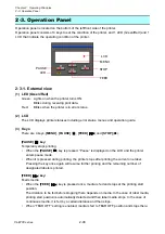
• When an optional auto cutter unit is installed, media is fed to the cut position and then
cutter unit is activated. Cutting operation is done for each feed.
• When an optional peeler unit is installed, media is fed to the peeling position.
Note that the
[FEED]
(
) key does not work if media is already set in the peeling position.
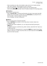
[STOP]
(
■
)
key:
Stops printing or cancels an error.
• When
the
[STOP]
(
■
) key is pressed during printing, the printer enters pause mode after
printing the current one label. In pause mode, if the
[STOP]
(
■
) key is pressed for more
than 4 seconds, 1 batch of printing job is cancelled.
The LCD displays “Job Clear” during cancel.
[MENU] key:
Enters menu setup mode or reissues the last label.
• When
the
[MENU]
key is pressed in on-line ready status, the printer enters menu
configuration mode.
• By changing the printer configuration, you can reissue the last label by pressing the
[MENU]
key.
To enable this function, set the “Menu Key Action” submenu under “After Print” main menu
to “Repeat Last One”.
Once you have set to “Repeat Last One”, pressing the
[MENU]
key reissues the last label.
However, in this case, to enter menu setup mode, you need to press and hold the
[MENU]
key for more than 4 seconds.
Содержание CL-E700 Series
Страница 1: ...Technical Manual CL E700 series Thermal Transfer Printer...
Страница 5: ...Chapter 1 Specifications 1 1 CL E700 series CHAPTER 1 SPECIFICATIONS...
Страница 15: ...Chapter 2 Operating Principles 2 1 CL E700 series CHAPTER 2 OPERATING PRINCIPLES...
Страница 87: ...Chapter 3 Disassembly and Maintenance 3 1 CL E700 series CHAPTER 3 DISASSEMBLY AND MAINTENANCE...
Страница 151: ...Chapter 4 Troubleshooting 4 1 CL E700 series CHAPTER 4 TROUBLESHOOTING...
Страница 167: ...Chapter 5 Parts Lists CL E700 series CHAPTER 5 PARTS LISTS...
Страница 172: ...Chapter 5 Parts Lists CL E700 series 5 6 DRAWING NO 1 General Assembly Rev 0...
Страница 195: ...Chapter 5 Parts Lists 5 29 CL E700 series DRAWING NO 7 Unit Opepane Rev 0...
Страница 203: ...Chapter 5 Parts Lists 5 37 CL E700 series DRAWING NO 9 SA2 Ribbon Unit Fan Rev 0...
Страница 206: ...Chapter 5 Parts Lists CL E700 series 5 40 DRAWING NO 10 Accessories Rev 0 3 2 4 1 1 1 2 1 3...
Страница 208: ...Chapter 6 Circuit Diagrams 6 1 CL E700 series CHAPTER 6 CIRCUIT DIAGRAMS...
Страница 230: ...Appendices AP 1 CL E700 series APPENDICES...
Страница 232: ...Appendices A Mounting Diagrams AP 3 CL E700 series A Mounting Diagrams A 1 SA Main PCB 1 Parts side...
Страница 233: ...Appendices A Mounting Diagrams CL E700 series AP 4 2 Solder side...

