Chapter 3 Disassembly and Maintenance
3-7. Adjustments
3-
51
CL-E700
series
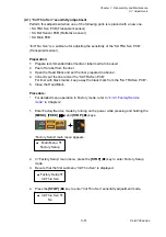
(2-1) “Init Thru Sen” sensitivity adjustment
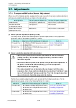
Perform this adjustment when one of the following parts is replaced with a new one.
• SA TRA Sen PCB (Transparent sensor)
• SA Ref Sensor PCB (Reflective sensor)
• SA Main PCB
“Init Thru Sen” is a submenu for adjusting the sensitivity of the “SA TRA Sen PCB”
(Transparent sensor).
Preparation:
1. Prepare recommended label media or label media to be used.
2. Peel off a label from the liner.
3. Open the Head Block and set the liner prepared in above 2.
4. Correctly put the liner under the “SA TRA Sen PCB”.
For liner with black marks, keep away the black mark from the “SA TRA Sen PCB”.
5. Close the Head Block.
Procedure:
*
For detailed menu operation in Factory mode, refer to “
” in Chapter 2.
1. Enter Factory/Service mode by turning on the power while pressing and holding the
[MENU]
,
[FEED]
(
) and
[STOP]
(
■
) keys.
“Factory Setup” main menu appears.
2. In “Factory Setup” main menu, press the
[STOP]
(
■
) key to enter Factory Setup
mode.
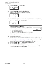
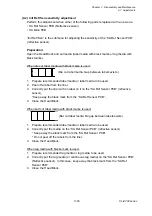
3. Be sure that the first submenu “Init Thru Sen” is displayed.
4. Press
the
[STOP]
(
■
) key to enter “Init Thru Sen” sensitivity adjustment mode.
Init Thru Sen
No
Factory Setup
Init Thru Sen
Main Menu
Factory Setup
Содержание CL-E700 Series
Страница 1: ...Technical Manual CL E700 series Thermal Transfer Printer...
Страница 5: ...Chapter 1 Specifications 1 1 CL E700 series CHAPTER 1 SPECIFICATIONS...
Страница 15: ...Chapter 2 Operating Principles 2 1 CL E700 series CHAPTER 2 OPERATING PRINCIPLES...
Страница 87: ...Chapter 3 Disassembly and Maintenance 3 1 CL E700 series CHAPTER 3 DISASSEMBLY AND MAINTENANCE...
Страница 151: ...Chapter 4 Troubleshooting 4 1 CL E700 series CHAPTER 4 TROUBLESHOOTING...
Страница 167: ...Chapter 5 Parts Lists CL E700 series CHAPTER 5 PARTS LISTS...
Страница 172: ...Chapter 5 Parts Lists CL E700 series 5 6 DRAWING NO 1 General Assembly Rev 0...
Страница 195: ...Chapter 5 Parts Lists 5 29 CL E700 series DRAWING NO 7 Unit Opepane Rev 0...
Страница 203: ...Chapter 5 Parts Lists 5 37 CL E700 series DRAWING NO 9 SA2 Ribbon Unit Fan Rev 0...
Страница 206: ...Chapter 5 Parts Lists CL E700 series 5 40 DRAWING NO 10 Accessories Rev 0 3 2 4 1 1 1 2 1 3...
Страница 208: ...Chapter 6 Circuit Diagrams 6 1 CL E700 series CHAPTER 6 CIRCUIT DIAGRAMS...
Страница 230: ...Appendices AP 1 CL E700 series APPENDICES...
Страница 232: ...Appendices A Mounting Diagrams AP 3 CL E700 series A Mounting Diagrams A 1 SA Main PCB 1 Parts side...
Страница 233: ...Appendices A Mounting Diagrams CL E700 series AP 4 2 Solder side...


