Chapter 4 Troubleshooting
4-2. Troubleshooting
CL-E700 series
4-10
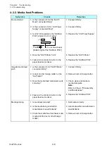
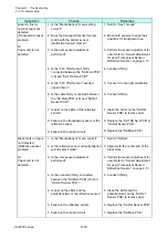
Symptoms
Checks
Remedies
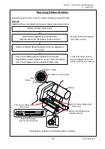
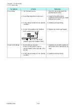
Ribbon slants.
1. Is the ribbon correctly inserted into the
ribbon holders?
2. Is the ribbon path correct?
3. Is the ribbon slant elimination
adjustment made?
1. Insert the ribbon correctly.
2. Re-install the ribbon correctly.
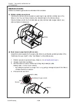
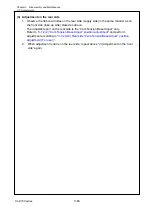
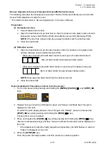
3. Adjust it according to “
Ribbon Slant Elimination
Adjustment
Ribbon slacks on the
take-up side.
“Error Ribbon Run” is
displayed on the
LCD.
1. Is the “SA Ribbon Tension Shaft F” to
give an adequate tension to the take-up
side ribbon correctly installed?
(Push it by hand and check if it moves
smoothly.)
2. Are the sensor projections incorporated
in the “SA Ribbon Tension Shaft F” free
from contacting with the
photointerrupters of the “SA Ribbon
Sensor”?
(Push the “SA Ribbon Tension Shaft F”
by hand and check if it moves smoothly.
For its operation, refer to “2-1-4. Ribbon
Feed Mechanism”.)
1. Install the “SA Ribbon Tension
Shaft F” correctly.
2. Replace the “SA Ribbon Tension
Shaft F” or the “SA Ribbon
Sensor”.
Содержание CL-E700 Series
Страница 1: ...Technical Manual CL E700 series Thermal Transfer Printer...
Страница 5: ...Chapter 1 Specifications 1 1 CL E700 series CHAPTER 1 SPECIFICATIONS...
Страница 15: ...Chapter 2 Operating Principles 2 1 CL E700 series CHAPTER 2 OPERATING PRINCIPLES...
Страница 87: ...Chapter 3 Disassembly and Maintenance 3 1 CL E700 series CHAPTER 3 DISASSEMBLY AND MAINTENANCE...
Страница 151: ...Chapter 4 Troubleshooting 4 1 CL E700 series CHAPTER 4 TROUBLESHOOTING...
Страница 167: ...Chapter 5 Parts Lists CL E700 series CHAPTER 5 PARTS LISTS...
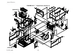
Страница 172: ...Chapter 5 Parts Lists CL E700 series 5 6 DRAWING NO 1 General Assembly Rev 0...
Страница 195: ...Chapter 5 Parts Lists 5 29 CL E700 series DRAWING NO 7 Unit Opepane Rev 0...
Страница 203: ...Chapter 5 Parts Lists 5 37 CL E700 series DRAWING NO 9 SA2 Ribbon Unit Fan Rev 0...
Страница 206: ...Chapter 5 Parts Lists CL E700 series 5 40 DRAWING NO 10 Accessories Rev 0 3 2 4 1 1 1 2 1 3...
Страница 208: ...Chapter 6 Circuit Diagrams 6 1 CL E700 series CHAPTER 6 CIRCUIT DIAGRAMS...
Страница 230: ...Appendices AP 1 CL E700 series APPENDICES...
Страница 232: ...Appendices A Mounting Diagrams AP 3 CL E700 series A Mounting Diagrams A 1 SA Main PCB 1 Parts side...
Страница 233: ...Appendices A Mounting Diagrams CL E700 series AP 4 2 Solder side...


