Chapter 4 Troubleshooting
4-2. Troubleshooting
4-15
CL-E700 series
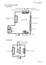
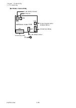
4-2-7. Connector Location
[SA Main PCB]
[SA Relay PCB]
USB2.0
J7
J4
J3
J8
J6
J5
J9
SA Main PCB
J14
To Interface Board
(Optional)
To Unit Power Supply
Front
To SA Opepane PCB
J10
J12
J13
J2
To SA TRA Sen PCB
To SA Ref Sensor PCB
To SA Relay PCB
To SA Head
To thermistor of "SA PF Motor"
To SA PF Motor
Ethernet
To SA Head Up Sensor PCB
J301
SA Relay PCB
To SA Main PCB
Front
To Peeler (Optional)
J303
J302
J304
To SA Ribbon Control PCB
To Cutter (Optional)
Содержание CL-E700 Series
Страница 1: ...Technical Manual CL E700 series Thermal Transfer Printer...
Страница 5: ...Chapter 1 Specifications 1 1 CL E700 series CHAPTER 1 SPECIFICATIONS...
Страница 15: ...Chapter 2 Operating Principles 2 1 CL E700 series CHAPTER 2 OPERATING PRINCIPLES...
Страница 87: ...Chapter 3 Disassembly and Maintenance 3 1 CL E700 series CHAPTER 3 DISASSEMBLY AND MAINTENANCE...
Страница 151: ...Chapter 4 Troubleshooting 4 1 CL E700 series CHAPTER 4 TROUBLESHOOTING...
Страница 167: ...Chapter 5 Parts Lists CL E700 series CHAPTER 5 PARTS LISTS...
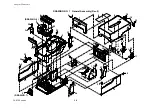
Страница 172: ...Chapter 5 Parts Lists CL E700 series 5 6 DRAWING NO 1 General Assembly Rev 0...
Страница 195: ...Chapter 5 Parts Lists 5 29 CL E700 series DRAWING NO 7 Unit Opepane Rev 0...
Страница 203: ...Chapter 5 Parts Lists 5 37 CL E700 series DRAWING NO 9 SA2 Ribbon Unit Fan Rev 0...
Страница 206: ...Chapter 5 Parts Lists CL E700 series 5 40 DRAWING NO 10 Accessories Rev 0 3 2 4 1 1 1 2 1 3...
Страница 208: ...Chapter 6 Circuit Diagrams 6 1 CL E700 series CHAPTER 6 CIRCUIT DIAGRAMS...
Страница 230: ...Appendices AP 1 CL E700 series APPENDICES...
Страница 232: ...Appendices A Mounting Diagrams AP 3 CL E700 series A Mounting Diagrams A 1 SA Main PCB 1 Parts side...
Страница 233: ...Appendices A Mounting Diagrams CL E700 series AP 4 2 Solder side...


