Chapter 3 Disassembly and Maintenance
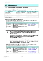
3-7. Adjustments
3-
61
CL-E700
series
Removing Ribbon Wrinkles
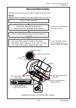
General procedure how to remove ribbon wrinkles is explained here.
General:
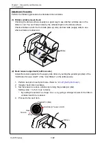
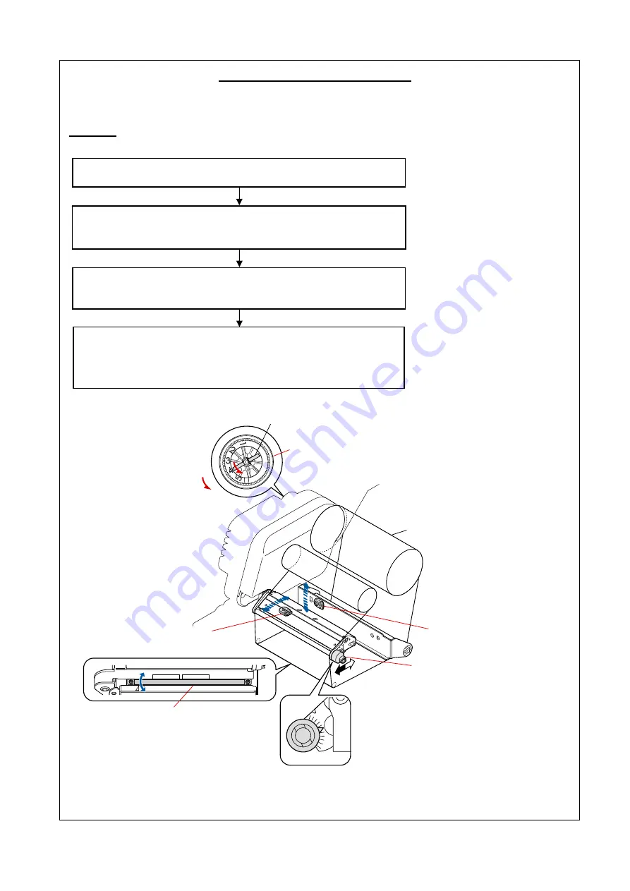
Adjustment flow and adjustment location diagram are shown below.
[Adjustment locations for eliminating ribbon wrinkles]
Back tension adjustment (Left/rear side)
(With the dial of the “SA Ribbon Tension Unit R“)
Ribbon Left-Right Balance Adjustment Knob adjustment
(For user)
• “Cam Tension Base Adjust” adjustment (Front side)
• “Shaft Ribbon Guide” adjustment (A part of the “SA Head”)
• “Cam Tension Base Adjust” adjustment (Rear side)
* Stronger tension will eliminate
more ribbon wrinkle.
* To eliminate ribbon wrinkles,
front side adjustment is more
effective than the rear side one.
Ribbon wrinkle visual check
Ribbon
Cam Tension Base Adjust
(Front side)
Cam Tension Base Adjust
(Rear side)
Ribbon Left-Right Balance
Adjustment Knob
SA Ribbon Tension Unit R
Parallel Pin (Dial)
Strong
Weak
Tension
Shaft Ribbon Guide
(A part of the "SA Head")
Содержание CL-E700 Series
Страница 1: ...Technical Manual CL E700 series Thermal Transfer Printer...
Страница 5: ...Chapter 1 Specifications 1 1 CL E700 series CHAPTER 1 SPECIFICATIONS...
Страница 15: ...Chapter 2 Operating Principles 2 1 CL E700 series CHAPTER 2 OPERATING PRINCIPLES...
Страница 87: ...Chapter 3 Disassembly and Maintenance 3 1 CL E700 series CHAPTER 3 DISASSEMBLY AND MAINTENANCE...
Страница 151: ...Chapter 4 Troubleshooting 4 1 CL E700 series CHAPTER 4 TROUBLESHOOTING...
Страница 167: ...Chapter 5 Parts Lists CL E700 series CHAPTER 5 PARTS LISTS...
Страница 172: ...Chapter 5 Parts Lists CL E700 series 5 6 DRAWING NO 1 General Assembly Rev 0...
Страница 195: ...Chapter 5 Parts Lists 5 29 CL E700 series DRAWING NO 7 Unit Opepane Rev 0...
Страница 203: ...Chapter 5 Parts Lists 5 37 CL E700 series DRAWING NO 9 SA2 Ribbon Unit Fan Rev 0...
Страница 206: ...Chapter 5 Parts Lists CL E700 series 5 40 DRAWING NO 10 Accessories Rev 0 3 2 4 1 1 1 2 1 3...
Страница 208: ...Chapter 6 Circuit Diagrams 6 1 CL E700 series CHAPTER 6 CIRCUIT DIAGRAMS...
Страница 230: ...Appendices AP 1 CL E700 series APPENDICES...
Страница 232: ...Appendices A Mounting Diagrams AP 3 CL E700 series A Mounting Diagrams A 1 SA Main PCB 1 Parts side...
Страница 233: ...Appendices A Mounting Diagrams CL E700 series AP 4 2 Solder side...


