Chapter 2 Operating Principles
2-3.
Operation Panel
CL-E700 series
2-54
2-3-3. Factory/Service mode
Factory mode and Service mode are available for maintenance work.
Factory mode:
You can change the factory-set items such as logical shift of the sensor or head.
Service mode:
You can perform checks such as head check and service counter value check to see the
media length printed.
In this section, the followings are explained.
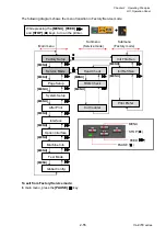
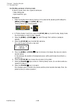
• How to enter Factory/Service Mode
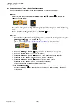
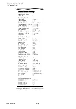
• How to print the Factory Mode Settings menus
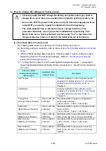
• How to change the settings in Factory mode
• How to operate submenus in Service mode
(1)
How to enter Factory/Service Mode
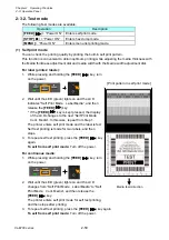
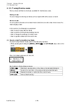
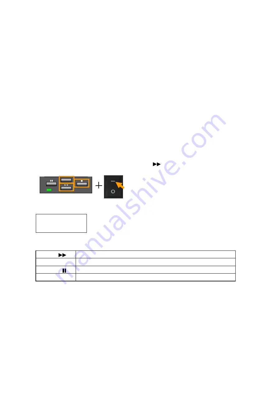
To enter Factory/Service mode, perform the following operation.
• While pressing and holding the
[MENU]
,
[FEED]
(
) and
[STOP]
(
■
) keys, turn on the
power.
Then, the following appears on the LCD.
Key function in Factory/Service mode:
[FEED]
(
)
Returns to previous item, or the value is incremented/changed.
[MENU]
Goes to the next item, or the value is decremented/changed.
[PAUSE]
( )
Resets the printer, or exits from the current menu.
[STOP]
(
■
)
Acts as the Enter key.
Main Menu
Factory Setup
Содержание CL-E700 Series
Страница 1: ...Technical Manual CL E700 series Thermal Transfer Printer...
Страница 5: ...Chapter 1 Specifications 1 1 CL E700 series CHAPTER 1 SPECIFICATIONS...
Страница 15: ...Chapter 2 Operating Principles 2 1 CL E700 series CHAPTER 2 OPERATING PRINCIPLES...
Страница 87: ...Chapter 3 Disassembly and Maintenance 3 1 CL E700 series CHAPTER 3 DISASSEMBLY AND MAINTENANCE...
Страница 151: ...Chapter 4 Troubleshooting 4 1 CL E700 series CHAPTER 4 TROUBLESHOOTING...
Страница 167: ...Chapter 5 Parts Lists CL E700 series CHAPTER 5 PARTS LISTS...
Страница 172: ...Chapter 5 Parts Lists CL E700 series 5 6 DRAWING NO 1 General Assembly Rev 0...
Страница 195: ...Chapter 5 Parts Lists 5 29 CL E700 series DRAWING NO 7 Unit Opepane Rev 0...
Страница 203: ...Chapter 5 Parts Lists 5 37 CL E700 series DRAWING NO 9 SA2 Ribbon Unit Fan Rev 0...
Страница 206: ...Chapter 5 Parts Lists CL E700 series 5 40 DRAWING NO 10 Accessories Rev 0 3 2 4 1 1 1 2 1 3...
Страница 208: ...Chapter 6 Circuit Diagrams 6 1 CL E700 series CHAPTER 6 CIRCUIT DIAGRAMS...
Страница 230: ...Appendices AP 1 CL E700 series APPENDICES...
Страница 232: ...Appendices A Mounting Diagrams AP 3 CL E700 series A Mounting Diagrams A 1 SA Main PCB 1 Parts side...
Страница 233: ...Appendices A Mounting Diagrams CL E700 series AP 4 2 Solder side...

