Chapter 2 Operating Principles
2-2.
Operation of Control Parts
CL-E700 series
2-22
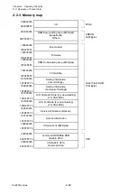
2-2-3. Memory map
00000000h
FPGA
000000FFh
I/O
0C000000h
SDRAM
32M
Bytes
0DFFFFFFh
RAM Downloading Area (4M Bytes)
Image Buffer
Others
18000000h
1802FFFFh
Boot Loader
18030000h
1834FFFFh
Firmware
18350000h
1874FFFFh
ROM Downloading Area (4M Bytes)
18760000h
1879FFFFh
FPGA Data
187A0000h
187AFFFFh
Setting Information
(User Settings)
Serial Flash ROM
187B0000h 16M
Bytes
187BFFFFh
Setting Information
(Factory-set Settings)
187C0000h
187CFFFFh
LCD Character Data (For downloading)
(For CSA/CSE)
187D0000h
187DFFFFh
LCD Font Data (For downloading)
(For CSA/CSE)
187E0000h
187EFFFFh
Service Information (Backup)
187F0000h
187FFFFFh
Service Information
18800000h
18FFFFFFh
Chinese Font (8M Bytes)
20000000h
202FFFFFh
Command RAM/Data RAM
(Built-in CPU)
CPU
20300000h
FFFFFFFFh
I/O (Built-in CPU)
Reserved Area
Содержание CL-E700 Series
Страница 1: ...Technical Manual CL E700 series Thermal Transfer Printer...
Страница 5: ...Chapter 1 Specifications 1 1 CL E700 series CHAPTER 1 SPECIFICATIONS...
Страница 15: ...Chapter 2 Operating Principles 2 1 CL E700 series CHAPTER 2 OPERATING PRINCIPLES...
Страница 87: ...Chapter 3 Disassembly and Maintenance 3 1 CL E700 series CHAPTER 3 DISASSEMBLY AND MAINTENANCE...
Страница 151: ...Chapter 4 Troubleshooting 4 1 CL E700 series CHAPTER 4 TROUBLESHOOTING...
Страница 167: ...Chapter 5 Parts Lists CL E700 series CHAPTER 5 PARTS LISTS...
Страница 172: ...Chapter 5 Parts Lists CL E700 series 5 6 DRAWING NO 1 General Assembly Rev 0...
Страница 195: ...Chapter 5 Parts Lists 5 29 CL E700 series DRAWING NO 7 Unit Opepane Rev 0...
Страница 203: ...Chapter 5 Parts Lists 5 37 CL E700 series DRAWING NO 9 SA2 Ribbon Unit Fan Rev 0...
Страница 206: ...Chapter 5 Parts Lists CL E700 series 5 40 DRAWING NO 10 Accessories Rev 0 3 2 4 1 1 1 2 1 3...
Страница 208: ...Chapter 6 Circuit Diagrams 6 1 CL E700 series CHAPTER 6 CIRCUIT DIAGRAMS...
Страница 230: ...Appendices AP 1 CL E700 series APPENDICES...
Страница 232: ...Appendices A Mounting Diagrams AP 3 CL E700 series A Mounting Diagrams A 1 SA Main PCB 1 Parts side...
Страница 233: ...Appendices A Mounting Diagrams CL E700 series AP 4 2 Solder side...

