Chapter 2 Operating Principles
2-2.
Operation of Control Parts
CL-E700 series
2-28
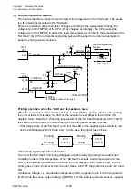
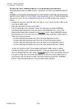
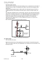
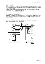
Abnormally high temperature detection:
To protect the “SA PF Motor” from being damaged, an abnormally high temperature detection
circuit is provided. If the temperature of the “SA PF Motor” exceeds a set temperature limit, the
LED on the operation panel blinks in red and the LCD displays “Error System Fail”, and the
printer goes off-line. To recover from the error status, turn OFF the printer once and then turn it
ON.
A reference voltage, i.e., an allowable temperature limit, is applied to pin 6 of the comparator
(U7B), while the sensor output voltage (TMPPF) from the PF motor temperature sensor is
applied to pin 5.
If the temperature of the “SA PF Motor” exceeds a certain level, the PF motor temperature
sensor output voltage becomes lower than the reference voltage, and the pin 7 of U7B goes to
“Low” level. At this time, pin K1 (nTMPERR) is “Low” and the FPGA (U5) detects an abnormally
high temperature.
In this abnormal state, the printer stops +24V DC supply to the “SA PF Motor”. Also, it stops
+24V DC supply to the “SA Head” and “SA Ribbon Motor F”.
Содержание CL-E700 Series
Страница 1: ...Technical Manual CL E700 series Thermal Transfer Printer...
Страница 5: ...Chapter 1 Specifications 1 1 CL E700 series CHAPTER 1 SPECIFICATIONS...
Страница 15: ...Chapter 2 Operating Principles 2 1 CL E700 series CHAPTER 2 OPERATING PRINCIPLES...
Страница 87: ...Chapter 3 Disassembly and Maintenance 3 1 CL E700 series CHAPTER 3 DISASSEMBLY AND MAINTENANCE...
Страница 151: ...Chapter 4 Troubleshooting 4 1 CL E700 series CHAPTER 4 TROUBLESHOOTING...
Страница 167: ...Chapter 5 Parts Lists CL E700 series CHAPTER 5 PARTS LISTS...
Страница 172: ...Chapter 5 Parts Lists CL E700 series 5 6 DRAWING NO 1 General Assembly Rev 0...
Страница 195: ...Chapter 5 Parts Lists 5 29 CL E700 series DRAWING NO 7 Unit Opepane Rev 0...
Страница 203: ...Chapter 5 Parts Lists 5 37 CL E700 series DRAWING NO 9 SA2 Ribbon Unit Fan Rev 0...
Страница 206: ...Chapter 5 Parts Lists CL E700 series 5 40 DRAWING NO 10 Accessories Rev 0 3 2 4 1 1 1 2 1 3...
Страница 208: ...Chapter 6 Circuit Diagrams 6 1 CL E700 series CHAPTER 6 CIRCUIT DIAGRAMS...
Страница 230: ...Appendices AP 1 CL E700 series APPENDICES...
Страница 232: ...Appendices A Mounting Diagrams AP 3 CL E700 series A Mounting Diagrams A 1 SA Main PCB 1 Parts side...
Страница 233: ...Appendices A Mounting Diagrams CL E700 series AP 4 2 Solder side...

