Chapter 3 Disassembly and Maintenance
3-5. Quick Detachment of Major Parts
3-7
CL-E700
series
1
2
3
4
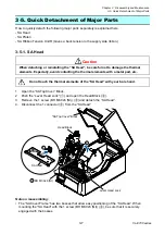
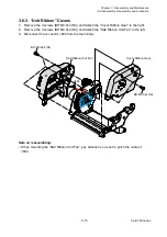
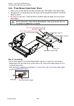
SA Head
BH M3.0x6 (NI)
Lever Head Lock
Head Block
"SA Top Cover" Block
3-5.
Quick Detachment of Major Parts
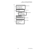
How to quickly detach the following major parts separately is explained here.
- SA Head
- SA Platen
- SA Ribbon Tension Unit R (Gives a back tension to the supply side ribbon.)
3-5-1. SA Head
When detaching or reinstalling the “SA Head”, be careful not to damage the thermal
elements. Especially, avoid contacting the thermal elements with a metal part, etc.
Do not touch the thermal elements of the “SA Head” with your bare hand.
1. Open the “SA Top Cover” Block.
2. Push the “Lever Head Lock” (
) and open the Head Block (
).
3. Remove the 1 screw (BH M3.0x6 (NI)) (
) and detach the “SA Head”.
4. Disconnect the 1 connector (
) from the “SA Head”.
Note on reassembling:
• The “SA Cover Frame” has two bosses that allow easy positioning of the “SA Head”. When
mounting the “SA Head” with the 1 screw (BH M3.0x6 (NI)) (
), be sure that it is securely
engaged with the bosses.
Caution
Содержание CL-E700 Series
Страница 1: ...Technical Manual CL E700 series Thermal Transfer Printer...
Страница 5: ...Chapter 1 Specifications 1 1 CL E700 series CHAPTER 1 SPECIFICATIONS...
Страница 15: ...Chapter 2 Operating Principles 2 1 CL E700 series CHAPTER 2 OPERATING PRINCIPLES...
Страница 87: ...Chapter 3 Disassembly and Maintenance 3 1 CL E700 series CHAPTER 3 DISASSEMBLY AND MAINTENANCE...
Страница 151: ...Chapter 4 Troubleshooting 4 1 CL E700 series CHAPTER 4 TROUBLESHOOTING...
Страница 167: ...Chapter 5 Parts Lists CL E700 series CHAPTER 5 PARTS LISTS...
Страница 172: ...Chapter 5 Parts Lists CL E700 series 5 6 DRAWING NO 1 General Assembly Rev 0...
Страница 195: ...Chapter 5 Parts Lists 5 29 CL E700 series DRAWING NO 7 Unit Opepane Rev 0...
Страница 203: ...Chapter 5 Parts Lists 5 37 CL E700 series DRAWING NO 9 SA2 Ribbon Unit Fan Rev 0...
Страница 206: ...Chapter 5 Parts Lists CL E700 series 5 40 DRAWING NO 10 Accessories Rev 0 3 2 4 1 1 1 2 1 3...
Страница 208: ...Chapter 6 Circuit Diagrams 6 1 CL E700 series CHAPTER 6 CIRCUIT DIAGRAMS...
Страница 230: ...Appendices AP 1 CL E700 series APPENDICES...
Страница 232: ...Appendices A Mounting Diagrams AP 3 CL E700 series A Mounting Diagrams A 1 SA Main PCB 1 Parts side...
Страница 233: ...Appendices A Mounting Diagrams CL E700 series AP 4 2 Solder side...

