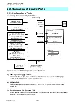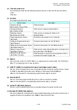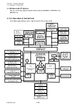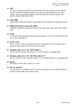
Chapter 2 Operating Principles
2-2.
Operation of Control Parts
2-27
CL-E700 series
to pin 3.
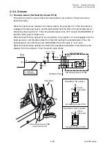
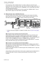
If the temperature of the “SA Head” exceeds 100
C (212
F), the head temperature sensor
output voltage becomes lower than the reference voltage, and pin 1 of U7A goes to “Low” level.
At this time, pin K1 (nTMPERR) is “Low” and the FPGA (U5) detects an abnormally high
temperature.
In this abnormal state, the printer stops +24V DC supply to the “SA Head”. Also it stops +24V
DC supply to the “SA PF Motor” and “SA Ribbon Motor F”.
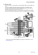
(4)
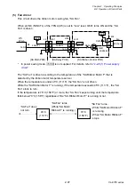
PF motor temperature sensor
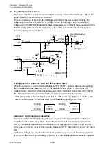
The PF motor temperature sensor is used to detect the temperature of the “SA PF Motor”. This
sensor is a thermistor bonded to the “SA PF Motor”.
Since the resistance of the thermistor changes according to the temperature change, the
voltage at pin 97 (TMPPF) of the CPU (U1A) changes accordingly. The CPU senses the
voltage at pin 97 (TMPPF) to detect the temperature of the “SA PF Motor”.
Printing operation when the “SA PF Motor” temperature rises:
When the temperature of the “SA PF Motor” rises to 95
C (203
F), printing speed is reduced to
avoid overheating. If it reaches 105°C (221°F), the “SA PF Motor” stops after printing the
current label. In this case, the LED on the operation panel blinks in red and the LCD displays
“Error PFMotor Hot”, and the printer goes off-line.
When the temperature of the “SA PF Motor” falls below 90
C (194
F), the LED and LCD
returns to normal display, and printing automatically resumes.
90°C
(194°F)
95°C
(203°F)
Normal speed
(Stop)
Normal speed
Normal speed
105°C
(221°F)
Low speed
(Stops)
(Stop)
1
J6
M
[SA PF Motor]
2
Thermistor
R85
C126
R86
PF Motor
Temperature Sensor
TMPPF
AN3
97
U7B
-
+
5
6
7
+3.3V
+3.3V
[SA Main PCB]
TEMP ERROR Detection
TMPPF
BA2903SFVM
R34
+3.3V
R32
C49
R33
N3
K1
33_N3
21_K1
FPGA
nTMPERR
nTMPENB
Error: Low
U5
nTMPERR
CPU
U1A
(L: Disables ribbon motor drive.)
Содержание CL-E700 Series
Страница 1: ...Technical Manual CL E700 series Thermal Transfer Printer...
Страница 5: ...Chapter 1 Specifications 1 1 CL E700 series CHAPTER 1 SPECIFICATIONS...
Страница 15: ...Chapter 2 Operating Principles 2 1 CL E700 series CHAPTER 2 OPERATING PRINCIPLES...
Страница 87: ...Chapter 3 Disassembly and Maintenance 3 1 CL E700 series CHAPTER 3 DISASSEMBLY AND MAINTENANCE...
Страница 151: ...Chapter 4 Troubleshooting 4 1 CL E700 series CHAPTER 4 TROUBLESHOOTING...
Страница 167: ...Chapter 5 Parts Lists CL E700 series CHAPTER 5 PARTS LISTS...
Страница 172: ...Chapter 5 Parts Lists CL E700 series 5 6 DRAWING NO 1 General Assembly Rev 0...
Страница 195: ...Chapter 5 Parts Lists 5 29 CL E700 series DRAWING NO 7 Unit Opepane Rev 0...
Страница 203: ...Chapter 5 Parts Lists 5 37 CL E700 series DRAWING NO 9 SA2 Ribbon Unit Fan Rev 0...
Страница 206: ...Chapter 5 Parts Lists CL E700 series 5 40 DRAWING NO 10 Accessories Rev 0 3 2 4 1 1 1 2 1 3...
Страница 208: ...Chapter 6 Circuit Diagrams 6 1 CL E700 series CHAPTER 6 CIRCUIT DIAGRAMS...
Страница 230: ...Appendices AP 1 CL E700 series APPENDICES...
Страница 232: ...Appendices A Mounting Diagrams AP 3 CL E700 series A Mounting Diagrams A 1 SA Main PCB 1 Parts side...
Страница 233: ...Appendices A Mounting Diagrams CL E700 series AP 4 2 Solder side...

