background image

21

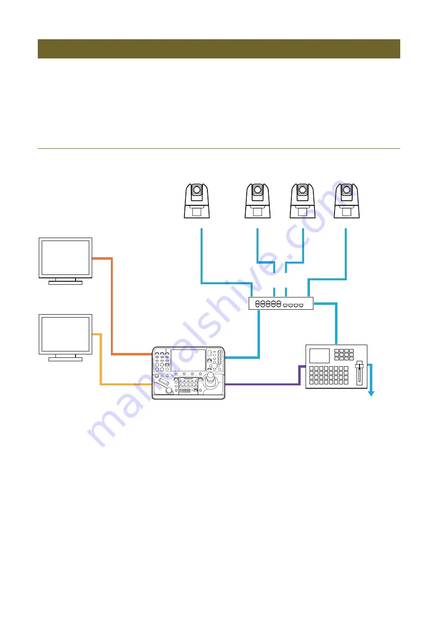
This section explains system configuration examples, as well as power supply methods. Communication with cameras* is 

done using XC protocol for IP connections, and NU protocol for serial connections.

* In the example below, the terms “IP camera” and “serial camera” are used for convenience depending on the connection type for 

communication with the camera. 

IP Connection System Example (Multiple Remote Cameras)

For IP Video Transmission

Connections

 Monitor

 PoE+ hub

IP Camera

IP 

S

witcher

Monitor

Device

IP Camera

IP Camera

IP Camera

 Video

 Video

 Video 

 Video

 Video

Video 


 Control

Control 

LAN

 Control

Control 

Video 

Control 

 Control

GPIO

HDMI OUT

S

DI OUT

LAN

LAN

LAN

LAN


S

treaming/

recording

 Video 

Содержание RC-IP1000

Страница 1: ...ENGLISH Remote Camera Controller User Manual...

Страница 2: ...e may cause electric shock and fire Turn off the power when the product is not used for a long period of time Failing to follow the instructions may result in fire or electric shock Do not leave the p...

Страница 3: ...age due to the degradation of image quality or internal components Be sure to connect the ground wire to the GND terminal To prevent electrical shocks caused by electrical leakage be sure to connect a...

Страница 4: ...and its use Take appropriate network security measures to avoid security breaches To the full extent permitted by laws and regulations neither Canon Inc nor any of its subsidiaries or affiliates shall...

Страница 5: ...splays and Basic Operations 25 Checking Operating the Top Menu 25 Changing Settings on the Menu 32 Checking Video on the PICTURE Screen 35 Connection Settings for the Device 38 Network Settings for th...

Страница 6: ...Cropping Frame on the Screen 55 Adjusting the Cropping Frame s Position Size 55 Selecting the Cropping Frame to be Applied to the Camera s Output Video 56 Operating the Device Using the Multi Camera...

Страница 7: ...Chapter Introduction This section explains how to read this manual as well as the names of parts of the device and their functionality...

Страница 8: ...he contents in this manual However should you have any comments concerning the information please contact our customer service center 4 Notwithstanding 2 and 3 above we shall not be liable for any imp...

Страница 9: ...device s POWER switch is turned on 2 ALARM Lamp Illuminates when an alarm is received from the camera Names of Parts and their Functions USER Buttons Area 1 Pan Tilt Operation Area CAMERA PRESET Sele...

Страница 10: ...menu 8 SYSTEM Menu Button Displays the SYSTEM menu P 60 Press it again to return to the top menu 9 CAMERA Menu Button Displays the CAMERA menu P 72 Press it again to return to the top menu 10 SET Butt...

Страница 11: ...n CAMERA PRESET Select Area 14 CAMERA GROUP Lamp PRESET GROUP Lamp Indicates the current selection CAMERA CAMERA GROUP or PRESET PRESET GROUP CAMERA GROUP Lamp PRESET GROUP Lamp 13 Condition Illuminat...

Страница 12: ...g a button while the F4 dial is pressed deletes the button s preset 17 SELECT Button Used to choose the selection target for CAMERA PRESET Select Buttons 1 10 Every time the SELECT button is pressed t...

Страница 13: ...an Direction and Tilt Direction P 62 in the SYSTEM menu During cropping frame adjustment mode P 55 it is used to adjust the position of the cropping frame 21 USER 5 Button Performs the function assign...

Страница 14: ...ping frame 28 Iris Zoom Focus Operation Area ENABLE Button Enables or disables operation of the Iris Zoom Focus Operation Area 29 AUTO Focus Button Switches the focus adjustment method between automat...

Страница 15: ...pprox 5 600 K 38 ABB Button Used for future expansion 39 AWB Button Switches the white balance mode to automatic Pressing and holding down the button switches the color temperature to the one set for...

Страница 16: ...he Camera Settings Area 44 MASTER PED Dial Adjusts the CAMERA menu Black Master Pedestal P 74 settings Turning the dial clockwise increases the value Pressing the dial resets the value to 0 Condition...

Страница 17: ...d 51 USB Terminal Rear You can connect a USB memory to the terminal You can use a USB memory formatted with FAT32 or exFAT 52 HDMI OUT Terminal Terminal for HDMI output 53 SDI OUT Terminal Terminal fo...

Страница 18: ...Chapter Preparations This chapter explains the installation connection and initialization of the device...

Страница 19: ...INTAKE as follows AIR INTAKE 20 mm 0 79 in or more 50 mm 1 97 in or more around the center of the fan EXHAUST VENT 20 mm 0 79 in or more EXHAUST VENT AIR INTAKE 20 mm or more 0 79 in or more 20 mm or...

Страница 20: ...0 02 in Make sure that cables can be connected or disconnected from each terminal after being embedded in the desktop 2 Attach the mount angles to both sides of the device using four 6 mm 0 24 in lon...

Страница 21: ...nd serial camera are used for convenience depending on the connection type for communication with the camera IP Connection System Example Multiple Remote Cameras For IP Video Transmission Connections...

Страница 22: ...hub IP Camera Switcher Monitor Device IP Camera IP Camera IP Camera Video Video Control LAN Control GPIO HDMI OUT SDI OUT Control LAN Video SDI IN Video SDI IN Control LAN Streaming recording Monitor...

Страница 23: ...onitor Device IP Camera Video Video Video Video Video Video Video Control Video Control TALLY Control GPIO HDMI OUT SDI OUT SDI IN LAN LAN LAN Serial Camera Serial Camera Video Control SDI IN Control...

Страница 24: ...tatus page of the top menu is displayed on the LCD panel when startup is complete You can change the displayed screen from Initial Screen in the SYSTEM menu P 63 Note After turning on the power do not...

Страница 25: ...settings are displayed and can be changed 4 Color Adjustment Settings White balance R gain B gain Master Black Red Blue and Master Pedestal setting values are displayed 5 Assigned Functions for the F1...

Страница 26: ...he edges of the bar 13 Screen Switch Buttons Current Screen Position Total Screen Number Pressing the button switches to the next screen in the following order pressing the button switches to the prev...

Страница 27: ...USER 1 to USER 10 are displayed Press the desired button to execute the assigned function or to switch the setting value In the case of functions with an on off status when set to on the background co...

Страница 28: ...tered not selected Camera registered selected Camera registered Control target Camera registered selected Camera not registered not selected Camera not registered not selected Camera not registered se...

Страница 29: ...Number The camera number of 10 cameras in the currently selected group is displayed 3 Preset Button You can execute presets 1 to 5 registered on each camera Buttons are displayed in the same way as i...

Страница 30: ...cutes tracing simultaneously on cameras that are ready to trace 2 Assigned Functions F1 F3 and Setting Values Turn the dials to change the settings and press them to execute a function Setting items a...

Страница 31: ...ge You can also switch lists using the buttons on the menu operation area 3 Preset Display Number Switch Button Switches the amount of preset buttons shown per page between 20 and 50 When showing 50 b...

Страница 32: ...g Settings on the Menu You can set various functions of the device using the menu This section explains basic menu operations 1 Menu Name Camera Number Camera Name The current menu name and the select...

Страница 33: ...ab page switch buttons to switch the page or touch the desired tab button The line number button and setting items of the selected line will be displayed in orange and the current setting values will...

Страница 34: ...Characters that cannot be used for setting items displayed in gray cannot be entered 6 Turn the dial operated on step 5 to select the desired setting value then press the SET button or touch the desir...

Страница 35: ...the setting item For items with sub setting items Focus Crop Add On press the dial to access the settings To go back select Back Single View Checking Display input video from the SDI IN terminal or in...

Страница 36: ...he CAMERA menu P 75 HDMI 3G SDI Add On Controls Add On Auto Tracking Same as the item of the same name in the CAMERA menu P 76 Status Auto Loop Setting item Setting Values Description 2x2 Display 3x3...

Страница 37: ...ngle Therefore frames will not be displayed in the correct position if the viewing angle is not displayed entirely such as when cropped SDI input video is displayed Icon Display Description Camera num...

Страница 38: ...ng settings IPv4 Address Subnet Mask Default Gateway For reference Inputting the IP Address P 41 IPv6 Address Prefix Length Default Gateway Note For settings information when performing manual setting...

Страница 39: ...cted Cameras Automatically Already set up cameras connected to the same network as the device are registered automatically in one go via IP connection Up to 200 cameras connected via IP connection can...

Страница 40: ...ired for options other than IP connection Cameras in the same network that are not registered to the selected group are searched and displayed in a list When configuring network settings manually proc...

Страница 41: ...turn the F1 F4 dials to input numbers If you touch Cancel or press the BACK button the input operation will be interrupted Note When inputting an IPv6 address select IPv6 Address to display the IPv6 a...

Страница 42: ...era Issued by Issued to Validity Period Start Date and Validity Period End Date for the imported certificate are displayed 1 Select the SYSTEM menu Camera Connection tab P 64 2 Connect the USB memory...

Страница 43: ...registered to an unused camera number If you cannot connect to a camera using an IPv4 address register using an IPv6 address Note After setup some system settings such as the output signal format can...

Страница 44: ...tion screen is displayed The power of the cameras specified as target will change to on or standby Using the CAMERA PRESET Select Buttons to Control Camera Power On Standby During camera selection mod...

Страница 45: ...Chapter Operation This chapter explains basic operations of the device CAMERA PRESET selection and camera operation...

Страница 46: ...ted cameras For details on camera power control refer to Controlling Camera Power On Standby P 44 The last camera group selected is remembered Checking the Basic Operation Procedure 1 Turning on the d...

Страница 47: ...elect buttons illuminate in blue To select camera groups from number 11 onwards press the SELECT button again the 11 20 lamp will illuminate When illuminated the CAMERA PRESET Select buttons 1 10 and...

Страница 48: ...es and the preset group select mode PRESET GROUP lamp illuminated in blue will be activated The non selected CAMERA PRESET Select buttons illuminate in blue The preset group is selected and the corres...

Страница 49: ...e a camera s menu displayed on an external monitor to change camera settings from the device Changing Camera Settings 1 Connect the camera s SDI output to the device s SDI IN terminal 2 Display the PI...

Страница 50: ...king Press the F2 dial Cancel Tracking to cancel tracking Proceed to step 6 Touch Focus Adjustment During Manual Focus on a Compatible Camera appears on the touched position and focus is performed Pro...

Страница 51: ...ontrol is performed using the status of the currently selected camera as the base If the model or status of cameras to be controlled is different the operated function may not work Selecting cameras t...

Страница 52: ...may take some time Changing Power and Basic Settings for Multiple Cameras You can simultaneously power on off or change various settings of either cameras in the selected group or all cameras Group Ca...

Страница 53: ...0p RGB444 12 bit 10 bit 3840x2160 25 00p YCbCr444 12 bit 10 bit 3840x2160 23 98p YCbCr422 12 bit 3840x2160 23 98p RGB444 12 bit 10 bit 3840x2160 23 98p YCbCr444 12 bit 10 bit 6G SDI 3840x2160 29 97p Y...

Страница 54: ...ching superimposed displays interrupts the video momentarily Formats Supported by the HDMI OUT Terminal Only video is output from the HDMI OUT terminal Audio is not output Switch the output format acc...

Страница 55: ...ck to the previous level Adjusting the Cropping Frame s Position Size The selected cropping frame is displayed in yellow or green Frames with corner icons can be resized You can also touch the LCD pan...

Страница 56: ...ay select the cropping frame or select the frame to be operated from the CAMERA menu Crop tab P 75 5 For cropping frames with adjustable size press the ZOOM rocker to adjust the size 6 Press the pan t...

Страница 57: ...l that can be used to communicate with the application Select Off to disable control from the application Set the user name and password of the device Used when accessing from the application For refe...

Страница 58: ...Chapter Menu This chapter explains the menu settings of the device...

Страница 59: ...s etc 69 Trace List Trace list display execution 70 Edit Trace Start stop trace recording recording settings etc 71 Multi Preset Multi Preset registration execution etc 71 CAMERA Menu Exposure Shootin...

Страница 60: ...1024 ISO Gain High Sensitivity Mode Manual WB Mode Sets White Balance tab Mode to Manual Focus Frame Display Operates Focus tab Frame Display Gamma Operates the menu item of the same name Color Space...

Страница 61: ...STBY Operates the menu item of the same name Push PTZ Max Speed While pressed operates pan tilt zoom at maximum speed regardless of the pan tilt SPEED dial and zoom SPEED dial settings Home Position S...

Страница 62: ...ection settings for pan tilt zoom focus and iris and the setting target for the F5 dial Common Set for all controlled cameras Specify Individually Set for an individual camera Camera Camera 1 to Camer...

Страница 63: ...olume SDI Output Selects the SDI OUT terminal s output video selection method Through Outputs SDI video as is no onscreen displays Auto SDI Priority If there is SDI input video it is output If there i...

Страница 64: ...list of registered cameras Example Camera 1 192 160 100 1 Camera 2 Serial Tally When Selected On Off Turns on the PGM tally red of the camera selected from Registered Camera List Swap Source or Swap D...

Страница 65: ...for the device Setting item Setting values description Setting item Setting values description Camera Camera 1 to Camera 200 Camera 1 Selects the registration camera number for the camera Touch on th...

Страница 66: ...P addresses of the second and subsequent cameras are set in order by adding 1 or more to the address set in IPv4 Address Setting item Setting values description IPv4 Setting Method DHCP AutoIP Manual...

Страница 67: ...characters spaces and printable characters as the distinguished name of the certificate For Common Name CN a host name in FQDN format should be input required Valid Period Start Year Month Day Valid P...

Страница 68: ...et In 4 Multi Preset 1 to Multi Preset 5 Multi Preset 1 to 4 Selects Multi Presets to consider as input when receiving Multi Preset In Camera Out 1 to Camera Out 10 Camera 1 to 200 Camera 1 to 10 When...

Страница 69: ...s not support the specified speed mode the preset operates with Time sec Register Sets the items to be registered for the preset when Operation Mode is set to Add Same as Edit Set Preset Register Time...

Страница 70: ...reset 1 home on the remote camera It may take some time if the number or registered presets is high Freeze Image During Movement On Off Conform to Camera Set Freezes the camera image when movement sta...

Страница 71: ...l Stops the trace operation Delete Deletes the trace corresponding to the trace number selected in Trace Setting item Setting values description Multi Preset Multi Preset 1 to Multi Preset 5 Multi Pre...

Страница 72: ...de Manual Auto Fixed Extended ND Range On Off Shutter Mode Auto Speed Slow Clear Scan Angle Manual Off Shutter Speed sec Shutter Speed Hz Shutter Speed Depending on Shutter Mode selects the shutter sp...

Страница 73: ...Display Off On Face AF Face Detection During auto focus Face AF Off Face Only Face Det Tracking During manual focus Face Detection Off On Eye Detection Off On Face Detection AE Off On Touch Operation...

Страница 74: ...ow Key Satur Activate Level Activate Off On Level 50 to 50 Specifies how saturated colors are in dark areas Sharpness Level Detail Frequency Coring Level Limit Level 10 to 50 Detail Frequency 8 to 8 C...

Страница 75: ...18 Color correction for a specific range of tones Setting item Setting values description Setting item Setting values description Digital Zoom Off 300x 400x Digital Tele Converter Advanced Digital Tel...

Страница 76: ...disables automatic selection of the tracking target Auto Loop No 1 to 5 Auto Loop Stop Start Loop Operation Loop Back Forth Loop Direction Forward Reverse Loop Name Displays the loop name Save Saves...

Страница 77: ...er DISP Level 2 Shooting Information Display Markers Focus Frame Setting item Setting values description Peaking XXX Off On Peaking Peaking 1 Peaking 2 Peaking 1 Color White Red Yellow Blue Peaking 1...

Страница 78: ...ut volume IPv4 Address Inputs the IPv4 address Subnet Mask Inputs the subnet mask Default Gateway Inputs the default gateway address Apply Sets the System tab settings to the camera except for Camera...

Страница 79: ...Control Range Group All Selects target cameras to be controlled with the following functions Power On Turns the power on Standby Switches to standby Auto WB Mode Sets the white balance mode to AWB Sho...

Страница 80: ...Chapter Appendix This chapter explains the measures to take when trouble occurs or a log message is displayed...

Страница 81: ...an attempt to change a setting item that is not available with the current camera settings Depending on the status of the camera you may be able to set unavailable setting items operating sounds and...

Страница 82: ...camera s IP address Operation is not performed correctly when using multiple control methods controllers control application the camera s Settings Pages etc Camera communications operation control IP...

Страница 83: ...a camera in factory default state The camera you are trying to register is not factory set Connect register from the Camera Connection tab or Camera Connect Details tab A system error has been detecte...

Страница 84: ...4 5 Terminals RJ 45 connector x 5 Used for NU Protocol serial connection GPIO 1 Terminal GPIO 2 Terminal D sub 25 pin used for external device control interface USB Terminals front rear USB Type A x2...

Страница 85: ...GM Tally In 9 18 IN PGM Tally In 10 6 GND GND 19 IN PVW Tally In 1 Multi Preset In 1 Group 1 In 7 IN PVW Tally In 2 Multi Preset In 2 Group 2 In 20 IN PVW Tally In 3 Multi Preset In 3 Group 3 In 8 IN...

Страница 86: ...up Out 1 to 5 1 to 20 Output when the specified group is selected Status Multi Preset In 1 to 4 Multi Preset 1 to 4 The specified Multi Preset is executed when input is received Trigger Menu ENABLE Th...

Страница 87: ...8 IN OUT Camera Out 4 Camera In 4 Camera Button Out 4 21 IN OUT Camera Out 5 Camera In 5 Camera Button Out 5 9 IN OUT Camera Out 6 Camera In 6 Camera Button Out 6 22 IN OUT Camera Out 7 Camera In 7 C...

Страница 88: ...Terminal Pin Arrangement Pin number Function 1 RX Input 2 RX Input 3 TX Output 4 GND 5 GND 6 TX Output 7 NC 8 NC Connect the GNDs on both ends to stabilize the voltage level of the signal Pin number F...

Страница 89: ...n for desktop mounting angles Dimensions 5 0 20 317 12 48 342 13 47 8 0 32 245 9 65 115 4 53 56 2 21 145 5 71 Units mm inch 12 4 0 49 51 2 01 140 5 51 245 3 9 66 58 2 2 29 17 0 67 39 1 54 74 1 2 92 2...

Страница 90: ...DMI Logos are trademarks or registered trademarks of HDMI Licensing Administrator Inc All other company or product names used in this document are trademarks or registered trademarks of their respecti...

Страница 91: ...le Cameras Simultaneously 51 Crop 55 75 Cropping Camera Output Video 55 Cropping Frame 55 Custom Picture 73 D DC IN 12V Terminal 17 23 88 DC Power Supply 23 Desktop Mounting Angles 19 Dimensions 19 89...

Страница 92: ...lt Settings 62 PGM Tally 12 26 PICTURE Button 10 35 PICTURE Screen 35 Pin Arrangement 85 PoE 24 PoE Hub 21 PoE Restrictions 63 POWER 17 Power 44 POWER Switch 17 Powering On Off Multiple Cameras 52 PRE...

Страница 93: ...Device 24 Turning On the Power Camera 44 Turning On the Power of the Cameras 44 U USB Terminal 10 17 84 USER 1 10 Screen 27 USER Buttons 1 to 5 11 13 USER Buttons Area 11 Using the Menu for Camera Set...

Страница 94: ...DIE 0583 000 CANON INC 2023...

Отзывы: