


Chapter 17
17-36
F-17-17
3. LASER
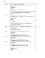
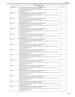
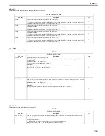
Laser Output Adjustment
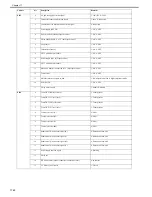
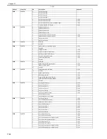
T-17-27
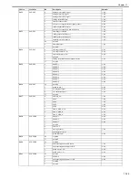
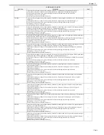
COPIER>ADJUST>LASER
Sub item
Description
level.
LA-PWR-A
Enter the laser power adjustment value for Laser A.
This machine adjusts the laser power at DMAX for PCRG initialization. This item adjusts the laser power Y. This can
be used to determine a cause of a density fault. When replacing the DCON PCB, enter the value corresponding to PCRG.
Setting range: 0 to 15
1
LA-PWR-B
Enter the laser power adjustment value for Laser B.
This machine adjusts the laser power at DMAX for PCRG initialization. This item adjusts the laser power Y. This can
be used to determine a cause of a density fault. When replacing the DCON PCB, enter the value corresponding to PCRG.
Setting range: 0 to 15
1
LA-PWR-C
Enter the laser power adjustment value for Laser C.
This machine adjusts the laser power at DMAX for PCRG initialization. This item adjusts the laser power Y. This can
be used to determine a cause of a density fault. When replacing the DCON PCB, enter the value corresponding to PCRG.
Setting range: 0 to 15
1
LA-PWR-D
Enter the laser power adjustment value for Laser D.
This machine adjusts the laser power at DMAX for PCRG initialization. This item adjusts the laser power Y. This can
be used to determine a cause of a density fault. When replacing the DCON PCB, enter the value corresponding to PCRG.
Setting range: 0 to 15
1
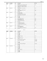
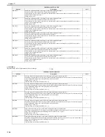
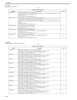
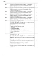
FSLUT-Y1
Partial ratio adjustment for Y-color images in the main scanning direction: 1
Correction value for the second block of partial ratio correction Y
When replacing the laser scanner unit, enter the value indicated on the label attached to the unit. When no value is
entered, color misalignment occurs.
Setting range: 0 to 99
1
FSLUT-Y2
Partial ratio adjustment for Y-color images in the main scanning direction: 2
Correction value for the second block of partial ratio correction Y
When replacing the laser scanner unit, enter the value indicated on the label attached to the unit. When no value is
entered, color misalignment occurs.
Setting range: 0 to 99
1
FSLUT-Y3
Partial ratio adjustment for Y-color images in the main scanning direction: 3
Correction value for the third block of partial ratio correction Y
When replacing the laser scanner unit, enter the value indicated on the label attached to the unit. When no value is
entered, color misalignment occurs.
Setting range: 0 to 99
1
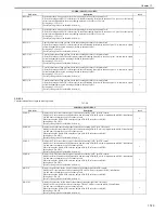
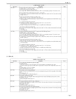
FSLUT-Y4
Partial ratio adjustment for Y-color images in the main scanning direction: 4
Correction value for the fourth block of partial ratio correction Y
When replacing the laser scanner unit, enter the value indicated on the label attached to the unit. When no value is
entered, color misalignment occurs.
Setting range: 0 to 99
1
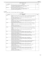
FSLUT-Y5
Partial ratio adjustment for Y-color images in the main scanning direction: 5
Correction value for the fifth block of partial ratio correction Y
When replacing the laser scanner unit, enter the value indicated on the label attached to the unit. When no value is
entered, color misalignment occurs.
Setting range: 0 to 99
1
FSLUT-Y6
Partial ratio adjustment for Y-color images in the main scanning direction: 6
Correction value for the sixth block of partial ratio correction Y
When replacing the laser scanner unit, enter the value indicated on the label attached to the unit. When no value is
entered, color misalignment occurs.
Setting range: 0 to 99
1
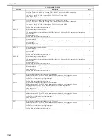
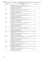
FSLUT-Y7
Partial ratio adjustment for Y-color images in the main scanning direction: 7
Correction value for the seventh block of partial ratio correction Y
When replacing the laser scanner unit, enter the value indicated on the label attached to the unit. When no value is
entered, color misalignment occurs.
Setting range: 0 to 99
1
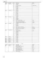
FSLUT-Y8
Partial ratio adjustment for Y-color images in the main scanning direction: 8
Correction value for the eighth block of partial ratio correction Y
When replacing the laser scanner unit, enter the value indicated on the label attached to the unit. When no value is
entered, color misalignment occurs.
Setting range: 0 to 99
1
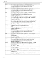
FSLUT-M1
Partial ratio adjustment for M-color images in the main scanning direction: 1
Correction value for the first block of partial ratio correction M
When replacing the laser scanner unit, enter the value indicated on the label attached to the unit. When no value is
entered, color misalignment occurs.
Setting range: 0 to 99
1
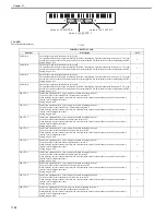
8 2 0 6 8 6 6 7 9 3 4 9
va l u e o f W- P L AT E - X
va l u e o f W- P L AT E - Y
va l u e o f W- P L AT E - Z
Содержание CiRC2550
Страница 2: ......
Страница 27: ...Chapter 1 Introduction ...
Страница 28: ......
Страница 47: ...Chapter 1 1 18 F 1 14 ON OFF ON OFF ...
Страница 70: ...Chapter 1 1 41 5 Turn on the main power switch ...
Страница 79: ...Chapter 2 Installation ...
Страница 80: ......
Страница 85: ...Chapter 2 2 3 Not available in some regions ...
Страница 134: ...Chapter 3 Basic Operation ...
Страница 135: ......
Страница 137: ......
Страница 143: ...Chapter 4 Main Controller ...
Страница 144: ......
Страница 152: ...Chapter 4 4 6 F 4 6 CPU HDD ROM access to the program at time of execution ...
Страница 171: ...Chapter 5 Original Exposure System ...
Страница 172: ......
Страница 203: ...Chapter 6 Laser Exposure ...
Страница 204: ......
Страница 206: ......
Страница 220: ...Chapter 7 Image Formation ...
Страница 221: ......
Страница 277: ...Chapter 8 Pickup Feeding System ...
Страница 278: ......
Страница 282: ......
Страница 336: ...Chapter 9 Fixing System ...
Страница 337: ......
Страница 339: ......
Страница 357: ...Chapter 10 Externals and Controls ...
Страница 358: ......
Страница 362: ......
Страница 366: ...Chapter 10 10 4 F 10 2 F 10 3 FM1 FM2 FM5 FM8 FM11 FM4 FM3 FM6 FM7 FM9 FM10 ...
Страница 375: ...Chapter 10 10 13 F 10 10 2 Remove the check mark from SNMP Status Enabled ...
Страница 376: ...Chapter 10 10 14 F 10 11 ...
Страница 402: ...Chapter 11 MEAP ...
Страница 403: ......
Страница 405: ......
Страница 452: ...Chapter 12 RDS ...
Страница 453: ......
Страница 455: ......
Страница 464: ...Chapter 13 Maintenance and Inspection ...
Страница 465: ......
Страница 467: ......
Страница 469: ...Chapter 13 13 2 F 13 1 8 9 1 2 3 3 5 6 7 10 11 12 13 14 4 ...
Страница 474: ...Chapter 14 Standards and Adjustments ...
Страница 475: ......
Страница 477: ......
Страница 485: ......
Страница 486: ...Chapter 15 Correcting Faulty Images ...
Страница 487: ......
Страница 495: ...Chapter 15 15 4 F 15 2 COLOR M 1 COLOR Y C K 0 ...
Страница 569: ...Chapter 15 15 78 F 15 82 J102 J107 J103 J108 J101 J109 J106 J112 J115 J113 J114 J104 J105 ...
Страница 570: ...Chapter 16 Self Diagnosis ...
Страница 571: ......
Страница 573: ......
Страница 600: ...Chapter 17 Service Mode ...
Страница 601: ......
Страница 603: ......
Страница 712: ...Chapter 18 Upgrading ...
Страница 713: ......
Страница 715: ......
Страница 746: ...Chapter 19 Service Tools ...
Страница 747: ......
Страница 748: ...Contents Contents 19 1 Service Tools 19 1 19 1 1 Special Tools 19 1 19 1 2 Solvents and Oils 19 2 ...
Страница 749: ......
Страница 752: ...APPENDIX ...
Страница 774: ......


