


Chapter 16
16-13
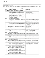
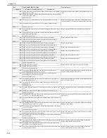
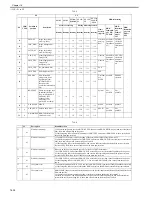
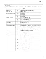
48XX CPU lock was detected at activation.
Remove and insert the main controller PCB (Sub RB-A).
Remove and insert the DDR-SDRAM. Replace the controller
PCB (Main).
When any of 4831, 4837, 4838, 4883, 4894, or 4854 occurred,
perform the measures shown above after performing the
following measures.
4831 CPU was locked at activation when ASIC initialization was performed for
each main controller PCB (Sub SJ-A/PDRM-EF-A/RO-A).
Remove and insert each main controller PCB (Sub SJ-A/
PDRM-EF-A/RO-A). Clean the terminal. Replace the
controller.
4837 CPU was locked at activation when ASIC initialization was performed for
each main controller PCB (Sub SJ-A/PDRM-EF-A/RO-A).
Remove and insert each main controller PCB (Sub SJ-A/
PDRM-EF-A/RO-A). Clean the terminal. Replace the
controller.
4838 CPU was locked at activation when ASIC initialization was performed for
each main controller PCB (Sub SJ-A/PDRM-EF-A/RO-A).
Remove and insert each main controller PCB (Sub SJ-A/
PDRM-EF-A/RO-A). Clean the terminal. Replace the
controller.
4854 CPU was locked at activation when ASIC initialization was performed for
each main controller PCB (Sub LAN-bar).
Remove and insert each main controller PCB (Sub LAN-bar).
Clean the terminal. Replace the controller.
4883 The CPU path was locked at activation when initialization was performed for
the main controller PCB (Sub RB-A) board.
Remove and insert the RB board. --> Replace the RB board. --
> Replace the main board.
4894 CPU was locked at activation when ASIC initialization was performed for
each main controller PCB (Sub SJ-A/PDRM-EF-A/RO-A).
Remove and insert each main controller PCB (Sub SJ-A/
PDRM-EF-A/RO-A). Clean the terminal. Replace the
controller.
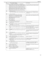
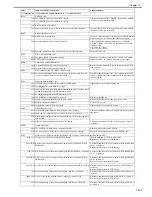
4910 A board different from the main controller PCB for the machine was detected. Replace the main controller PCB.
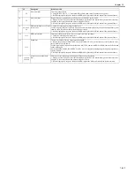
E749
Restart in accordance with a change of the product configuration
0001 The BootROM is replaced with a different type (when the PDL option is
installed) .
Turn OFF and back ON the main power to recover
0003 Replaced with other kind of BootROM (e.g. at installation of mAccele
accessory)
Recovered by turning the main power OFF / ON
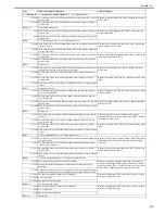
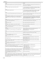
E804
Controller fan error
0000 Stop of power supply cooling fan was detected
Check the connection of power supply cooling fan, replace it
0001 Stop of power supply cooling fan 2 was detected
Check the connection of power supply cooling fan 2, replace it
0004 Stoppage of the controller fan is detected for 16 sec continuously.
Check on connection of the controller fan, Replace the
controller fan
E805
Fan error
0001 Lock fails to be detected for 5sec continuously while the exhaust fan (front) is
driven.
Disconnection of the fan connector. Lock signal fails to be sent due to a fan
failure.
Check on connection of the exhaust fan (front), Replace the
exhaust fan (front)
0002 Lock fails to be detected for 5sec continuously while the exhaust fan (rear) is
driven.
Disconnection of the fan connector. Lock signal fails to be sent due to a fan
failure.
Check on connection of the exhaust fan (rear), Replace the
exhaust fan (rear)
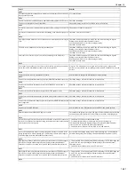
E806
Error in fan of main body
0001 Error in delivery adhesive fan was detected
Check the connection of delivery adhesive fan, replace it
0002 The drop of connector of delivery adhesive fan / the disconnection was
detected
Check the connection of delivery adhesive fan, replace it
0003 Error in secondary transfer exhaust fan was detected
Check the connection of secondary transfer exhaust fan, replace
it
E807
Error in fan of process cartridge
0001 Error in fan (front) of process cartridge was detected
Check the connection of fan (front) of process cartridge, replace
it
0002 Error in fan (rear) of process cartridge was detected
Check the connection of fan (rear) of process cartridge, replace
it
E808
Error in low-voltage power supply PCB (error in zero cross)
0000 Error in low-voltage power supply PCB
Replace low-voltage power supply PCB, replace DC controller
PCB
E811
Error in detection of new drum unit
0000 Error in blowout of fuse for detection of new drum unit (process cartridge)
Check the connection of drum unit, replace it
Replace DC driver PCB
0001 Error in blowout of fuse for detection of new drum unit (process cartridge)
Replace DC driver PCB
E840
Fan shutter error
0000 Fan shutter open/close operation Error
Cause
Abnormal rotation of the fan shutter motor
Defect of the fan shutter position sensor
Defect of the fan shutter home position error
Defect of the DC controller PCB
- Replace the fan shutter motor
- Replace the fan shutter position sensor
- Replace the fan shutter home position sensor
- Replace the DC controller PCB
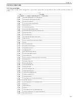
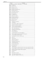
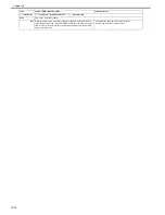
Code
Main Cause/Detail of Detection
Countermeasures
***: Finisher-Z1 ****: Finisher-Y1, Saddle Finisher-Y2 *****: Puncher Unit
Содержание CiRC2550
Страница 2: ......
Страница 27: ...Chapter 1 Introduction ...
Страница 28: ......
Страница 47: ...Chapter 1 1 18 F 1 14 ON OFF ON OFF ...
Страница 70: ...Chapter 1 1 41 5 Turn on the main power switch ...
Страница 79: ...Chapter 2 Installation ...
Страница 80: ......
Страница 85: ...Chapter 2 2 3 Not available in some regions ...
Страница 134: ...Chapter 3 Basic Operation ...
Страница 135: ......
Страница 137: ......
Страница 143: ...Chapter 4 Main Controller ...
Страница 144: ......
Страница 152: ...Chapter 4 4 6 F 4 6 CPU HDD ROM access to the program at time of execution ...
Страница 171: ...Chapter 5 Original Exposure System ...
Страница 172: ......
Страница 203: ...Chapter 6 Laser Exposure ...
Страница 204: ......
Страница 206: ......
Страница 220: ...Chapter 7 Image Formation ...
Страница 221: ......
Страница 277: ...Chapter 8 Pickup Feeding System ...
Страница 278: ......
Страница 282: ......
Страница 336: ...Chapter 9 Fixing System ...
Страница 337: ......
Страница 339: ......
Страница 357: ...Chapter 10 Externals and Controls ...
Страница 358: ......
Страница 362: ......
Страница 366: ...Chapter 10 10 4 F 10 2 F 10 3 FM1 FM2 FM5 FM8 FM11 FM4 FM3 FM6 FM7 FM9 FM10 ...
Страница 375: ...Chapter 10 10 13 F 10 10 2 Remove the check mark from SNMP Status Enabled ...
Страница 376: ...Chapter 10 10 14 F 10 11 ...
Страница 402: ...Chapter 11 MEAP ...
Страница 403: ......
Страница 405: ......
Страница 452: ...Chapter 12 RDS ...
Страница 453: ......
Страница 455: ......
Страница 464: ...Chapter 13 Maintenance and Inspection ...
Страница 465: ......
Страница 467: ......
Страница 469: ...Chapter 13 13 2 F 13 1 8 9 1 2 3 3 5 6 7 10 11 12 13 14 4 ...
Страница 474: ...Chapter 14 Standards and Adjustments ...
Страница 475: ......
Страница 477: ......
Страница 485: ......
Страница 486: ...Chapter 15 Correcting Faulty Images ...
Страница 487: ......
Страница 495: ...Chapter 15 15 4 F 15 2 COLOR M 1 COLOR Y C K 0 ...
Страница 569: ...Chapter 15 15 78 F 15 82 J102 J107 J103 J108 J101 J109 J106 J112 J115 J113 J114 J104 J105 ...
Страница 570: ...Chapter 16 Self Diagnosis ...
Страница 571: ......
Страница 573: ......
Страница 600: ...Chapter 17 Service Mode ...
Страница 601: ......
Страница 603: ......
Страница 712: ...Chapter 18 Upgrading ...
Страница 713: ......
Страница 715: ......
Страница 746: ...Chapter 19 Service Tools ...
Страница 747: ......
Страница 748: ...Contents Contents 19 1 Service Tools 19 1 19 1 1 Special Tools 19 1 19 1 2 Solvents and Oils 19 2 ...
Страница 749: ......
Страница 752: ...APPENDIX ...
Страница 774: ......


