


Chapter 15
15-51
5. If the symptom still occurs, replace the main controller PCB with a new one.
FM2-8258 HDD
FM2-9163 Main Controller PCB Assembly
15.3.7.27 E602-0113: HDD (hard disk) is faulty
0018-3212
Color iR C3380G / Color iR C2880G / Color iR C3380i / Color iR C3380 / Color iR C2880i / Color iR C2880 / iR C3480 / iR C3480i / iR C3080i / iR C2550
[ Inspected by Canon Inc. ]
Description
Since the progress bar stopped at the half point of the whole length and the error code "E602-0113" wad displayed, the HDD (hard disk) was replace with a
new one for solution.
- E602-0113 can be displayed when the HDD has a problem in the image data area (In-box, etc) during normal operation.
Cause
Because of a fault in the HDD, data in FSTDEV was corrupted.
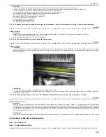
Field Remedy
1. In service mode > COPIER > Function > SYSTEM > CHK-TYPE, enter '0' using the numeric key, and press [OK]; then select [HD-CHECK] and press
[OK].
2. After executing [HD-CHECK] (time required: several min to several tens of min), turn the main power switch OFF and then ON.
3. If the symptom still occurs, format the HDD again using SST, and then re-install system software.
4. If the symptom still occurs, replace the HDD with a new one, and then install system software.
FM2-8258 HDD
15.3.7.28 E602-0002: Main Controller PCB (sub LANBER-C) is faulty
0018-3299
Color iR C3380G / Color iR C2880G / Color iR C3380i / Color iR C3380 / Color iR C2880i / Color iR C2880 / iR C3480 / iR C3480i / iR C3080i / iR C2550
[ Inspected by Canon Inc. ]
Description
Since the error code "E602-0002" was displayed, the main controller PCB (sub LANBER-C) was replaced with a new one for solution.
- E602-002 can be displayed when there is no system software for the main CPU (HDD error).
Cause
Since the main controller PCB (sub LANBER-C) was faulty, the data in the HDD was not read, causing E602-000.
Field Remedy
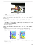
1. Re-fit the main controller PCB (sub LANBER-C), and J5002 and J5003 connectors of the main controller PCB (sub LANBER-C).
2. Re-fit J2121 and J2122 connectors of the HDD.
3. If the symptom still occurs, turn on the main power switch while pressing the numeric keys '2' and '8' on the control panel at the same time to start this
machine; then, format the HDD and install all system software (System, Lang, RUI) again using SST. Finally, turn the main power switch OFF/ON.
4. If the symptom still occurs, replace the main controller PCB (sub LANBER-C) with a new one.
5. If the symptom still occurs, suspect a failure of the HDD and replace the HDD. Then, format it and re-install system software with SST.
FM2-9611 LANBAR-C-BC PCB Assembly
FM2-8258 HDD
15.3.7.29 E611-0000: SRAM PCB is faulty
0018-0422
Color iR C3380G / Color iR C2880G / Color iR C3380i / Color iR C3380 / Color iR C2880i / Color iR C2880 / iR C3480 / iR C3480i / iR C3080i / iR C2550
[ Inspected by Canon Inc. ]
Description
Since the error code "E611-0000" was displayed, the SRAM PCB was replaced with a new one for solution.
- E611-0000 can be displayed when the SRAM data is corrupted and thus job data stored on the SRAM PCB cannot read out, which makes this machine
reboot repeatedly after recovery from power discontinuity.
Field Remedy
1. In service mode > COPIER > Function > MISC-P > P-PRINT, print out all the service settings.
2. Service mode > COPIER > Function > CLEAR > MN-CON > OK.
Note: Once this mode is executed, all the data stored on the SRAM PCB are initialized. As the file management information sent to the HDD is also initialized,
the image data on the HDD cannot be read out either. When executing this mode, explain this to the user and get their consent.
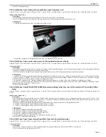
3. If the symptom still occurs, re-fit the SRAM PCB on the main controller PCB.
4. If the symptom still occurs, replace the SRAM PCB with a new one.
Note: When replacing the SRAM PCB, be sure to use the new PCB.
FM2-6209 DIMM (required by all models)
FM2-6208 DIMM (required only by 230V models)
15.3.7.30 E611-0000 occurs during startup (upon installation): SRAM PCB is faulty
0018-1343
Color iR C3380G / Color iR C2880G / Color iR C3380i / Color iR C3380 / Color iR C2880i / Color iR C2880 / iR C3480 / iR C3480i / iR C3080i / iR C2550
[ Inspected by Canon Inc. ]
Description
Since the error code "E611-0000" was indicated, the SRAM PCB was replaced with a new one for solution.
- E611-0000 can be displayed when SRAM data corruption prevents the job data stored in the SRAM PCB from being read out, consequently making this
machine repeat rebooting at recovery from power discontinuity.
Field Remedy
1. If this machine can enter service mode, make the following selections in sequence to clear SRAM data: service mode > COPIER > Function > CLEAR >
MN-CON > OK. Then, turn the main power switch OFF and then ON.
2. Re-fit the SRAM PCB.
3. If the symptom still occurs, replace the SRAM PCB with a new one.
Note: When replacing the SRAM PCB, be sure to use a new SRAM PCB.
FM2-6209 DIMM (required by all models)
FM2-6208 DIMM (required only by 230V models)
15.3.7.31 E674-0001/FAX function of Super G3 FAX Board-W1 does not work: Main controller PCB (main) is faulty
0018-1271
Color iR C3380G / Color iR C2880G / Color iR C3380i / Color iR C3380 / Color iR C2880i / Color iR C2880 / iR C3480 / iR C3480i / iR C3080i / iR C2550
Содержание CiRC2550
Страница 2: ......
Страница 27: ...Chapter 1 Introduction ...
Страница 28: ......
Страница 47: ...Chapter 1 1 18 F 1 14 ON OFF ON OFF ...
Страница 70: ...Chapter 1 1 41 5 Turn on the main power switch ...
Страница 79: ...Chapter 2 Installation ...
Страница 80: ......
Страница 85: ...Chapter 2 2 3 Not available in some regions ...
Страница 134: ...Chapter 3 Basic Operation ...
Страница 135: ......
Страница 137: ......
Страница 143: ...Chapter 4 Main Controller ...
Страница 144: ......
Страница 152: ...Chapter 4 4 6 F 4 6 CPU HDD ROM access to the program at time of execution ...
Страница 171: ...Chapter 5 Original Exposure System ...
Страница 172: ......
Страница 203: ...Chapter 6 Laser Exposure ...
Страница 204: ......
Страница 206: ......
Страница 220: ...Chapter 7 Image Formation ...
Страница 221: ......
Страница 277: ...Chapter 8 Pickup Feeding System ...
Страница 278: ......
Страница 282: ......
Страница 336: ...Chapter 9 Fixing System ...
Страница 337: ......
Страница 339: ......
Страница 357: ...Chapter 10 Externals and Controls ...
Страница 358: ......
Страница 362: ......
Страница 366: ...Chapter 10 10 4 F 10 2 F 10 3 FM1 FM2 FM5 FM8 FM11 FM4 FM3 FM6 FM7 FM9 FM10 ...
Страница 375: ...Chapter 10 10 13 F 10 10 2 Remove the check mark from SNMP Status Enabled ...
Страница 376: ...Chapter 10 10 14 F 10 11 ...
Страница 402: ...Chapter 11 MEAP ...
Страница 403: ......
Страница 405: ......
Страница 452: ...Chapter 12 RDS ...
Страница 453: ......
Страница 455: ......
Страница 464: ...Chapter 13 Maintenance and Inspection ...
Страница 465: ......
Страница 467: ......
Страница 469: ...Chapter 13 13 2 F 13 1 8 9 1 2 3 3 5 6 7 10 11 12 13 14 4 ...
Страница 474: ...Chapter 14 Standards and Adjustments ...
Страница 475: ......
Страница 477: ......
Страница 485: ......
Страница 486: ...Chapter 15 Correcting Faulty Images ...
Страница 487: ......
Страница 495: ...Chapter 15 15 4 F 15 2 COLOR M 1 COLOR Y C K 0 ...
Страница 569: ...Chapter 15 15 78 F 15 82 J102 J107 J103 J108 J101 J109 J106 J112 J115 J113 J114 J104 J105 ...
Страница 570: ...Chapter 16 Self Diagnosis ...
Страница 571: ......
Страница 573: ......
Страница 600: ...Chapter 17 Service Mode ...
Страница 601: ......
Страница 603: ......
Страница 712: ...Chapter 18 Upgrading ...
Страница 713: ......
Страница 715: ......
Страница 746: ...Chapter 19 Service Tools ...
Страница 747: ......
Страница 748: ...Contents Contents 19 1 Service Tools 19 1 19 1 1 Special Tools 19 1 19 1 2 Solvents and Oils 19 2 ...
Страница 749: ......
Страница 752: ...APPENDIX ...
Страница 774: ......


