


Chapter 17
17-47
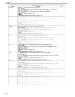
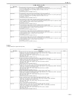
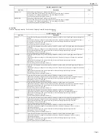
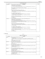
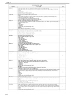
12. FEED-ADJ
T-17-36
1TR-TGM
Adjust the offset for the primary transfer ATVC target current (M)
Adjustment range: -10 to 10 (Unit: 1muA)
[Factory setting value/Value after RAM clear: 0]
This is valid when COPIER>OPTION>BODY>PTATVCSW=1 is set (the primary transfer ATVC control is valid).
Specify the offset amount of the primary transfer ATVC target current.
By executing ATVC operation after input, the control value is changed and is become valid. (It is executed by opening/
closing the front door.)
Perform the operation when the following symptoms occur:
- Image memory on the surface of the drum due to the transfer bias
The density at 95mm from the leading edge of image is dark. The symptom is significant with all-dark halftone image.
-> Set a smaller value
- Accordion-like dark short horizontal lines
Discharging trace caused by transfer at the succeeding station (Y, M, C, K, in this order).
-> Set a smaller value to the succeeding station.
Example: When symptom occurs with a Cyan image, set a smaller value to the Bk station.
- Poor transfer of the primary transfer roller
White strips with 55mm interval. With a highly-concentrated image, 5 to 10mm width horizontal white lines at the ends
of the image.
-> Set a larger value.
2
1TR-TGK1
Adjust the offset for the primary transfer ATVC target current (Bk: Black single mode)
Adjustment range: -10 to 10 (Unit: 1muA)
[Factory setting value/Value after RAM clear: 0]
This is valid when COPIER>OPTION>BODY>PTATVCSW=1 is set (the primary transfer ATVC control is valid).
Specify the offset amount of the primary transfer ATVC target current.
By executing ATVC operation after input, the control value is changed and is become valid. (It is executed by opening/
closing the front door.)
Perform the operation when the following symptoms occur:
- Image memory on the surface of the drum due to the transfer bias
The density at 95mm from the leading edge of image is dark. The symptom is significant with all-dark halftone image.
-> Set a smaller value
- Accordion-like dark short horizontal lines
Discharging trace caused by transfer at the succeeding station (Y, M, C, K, in this order).
-> Set a smaller value to the succeeding station.
Example: When symptom occurs with a Cyan image, set a smaller value to the Bk station.
- Poor transfer of the primary transfer roller
White strips with 55mm interval. With a highly-concentrated image, 5 to 10mm width horizontal white lines at the ends
of the image.
-> Set a larger value.
2
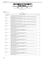
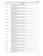
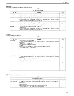
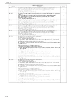
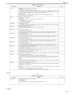
COPIER>ADJUST>FEED-ADJ
Sub item
Description
level.
REGIST
Used to adjust the registration roller clutch ON timing.
Adjustment method
- Increasing the value by 1 moves the image by 0.1 mm in the direction of the leading edge of the paper.
- If you have cleared the DC controller PCB's RAM or replaced the DC controller PCB, enter the value on the service
label.
Adjustment range - 50 to 50 (0.1 mm units)
[Factory default/After RAM clear: -20]
1
REG-THCK
Registration clutch ON timing (thick paper)
Adjusts the margin on the leading edge (0.1mm scale) by adjusting the timing to turn ON the registration clutch for thick
paper.
Setting Range: 50 ~ -50
[Factory default value / post-RAM clear value: 0]
1
REG-OHT
Registration clutch ON timing (OHT)
Adjustment of the OHT registration clutch ON timing allows adjustment of the leading edge margin (unit: 0.1mm).
Setting range: -50 to 50
[Factory settings and after RAM clear: 0]
1
REG-DUP1
Second page registration clutch ON timing (plain paper)
Adjustment of the plain paper second page registration clutch ON timing allows adjustment of the second page leading
edge margin (unit: 0.1mm).
Setting range: -50 to 50
[Factory settings and after RAM clear: 0]
1
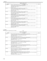
REG-DUP2
Second page registration clutch ON timing (thick paper)
Adjustment of the thick paper second page registration clutch ON timing allows adjustment of the second page leading
edge margin (unit: 0.1mm).
Setting range: -50 to 50
[Factory settings and after RAM clear: 0]
1
COPIER>ADJUST>HV-TR
Sub item
Description
Level.
Содержание CiRC2550
Страница 2: ......
Страница 27: ...Chapter 1 Introduction ...
Страница 28: ......
Страница 47: ...Chapter 1 1 18 F 1 14 ON OFF ON OFF ...
Страница 70: ...Chapter 1 1 41 5 Turn on the main power switch ...
Страница 79: ...Chapter 2 Installation ...
Страница 80: ......
Страница 85: ...Chapter 2 2 3 Not available in some regions ...
Страница 134: ...Chapter 3 Basic Operation ...
Страница 135: ......
Страница 137: ......
Страница 143: ...Chapter 4 Main Controller ...
Страница 144: ......
Страница 152: ...Chapter 4 4 6 F 4 6 CPU HDD ROM access to the program at time of execution ...
Страница 171: ...Chapter 5 Original Exposure System ...
Страница 172: ......
Страница 203: ...Chapter 6 Laser Exposure ...
Страница 204: ......
Страница 206: ......
Страница 220: ...Chapter 7 Image Formation ...
Страница 221: ......
Страница 277: ...Chapter 8 Pickup Feeding System ...
Страница 278: ......
Страница 282: ......
Страница 336: ...Chapter 9 Fixing System ...
Страница 337: ......
Страница 339: ......
Страница 357: ...Chapter 10 Externals and Controls ...
Страница 358: ......
Страница 362: ......
Страница 366: ...Chapter 10 10 4 F 10 2 F 10 3 FM1 FM2 FM5 FM8 FM11 FM4 FM3 FM6 FM7 FM9 FM10 ...
Страница 375: ...Chapter 10 10 13 F 10 10 2 Remove the check mark from SNMP Status Enabled ...
Страница 376: ...Chapter 10 10 14 F 10 11 ...
Страница 402: ...Chapter 11 MEAP ...
Страница 403: ......
Страница 405: ......
Страница 452: ...Chapter 12 RDS ...
Страница 453: ......
Страница 455: ......
Страница 464: ...Chapter 13 Maintenance and Inspection ...
Страница 465: ......
Страница 467: ......
Страница 469: ...Chapter 13 13 2 F 13 1 8 9 1 2 3 3 5 6 7 10 11 12 13 14 4 ...
Страница 474: ...Chapter 14 Standards and Adjustments ...
Страница 475: ......
Страница 477: ......
Страница 485: ......
Страница 486: ...Chapter 15 Correcting Faulty Images ...
Страница 487: ......
Страница 495: ...Chapter 15 15 4 F 15 2 COLOR M 1 COLOR Y C K 0 ...
Страница 569: ...Chapter 15 15 78 F 15 82 J102 J107 J103 J108 J101 J109 J106 J112 J115 J113 J114 J104 J105 ...
Страница 570: ...Chapter 16 Self Diagnosis ...
Страница 571: ......
Страница 573: ......
Страница 600: ...Chapter 17 Service Mode ...
Страница 601: ......
Страница 603: ......
Страница 712: ...Chapter 18 Upgrading ...
Страница 713: ......
Страница 715: ......
Страница 746: ...Chapter 19 Service Tools ...
Страница 747: ......
Страница 748: ...Contents Contents 19 1 Service Tools 19 1 19 1 1 Special Tools 19 1 19 1 2 Solvents and Oils 19 2 ...
Страница 749: ......
Страница 752: ...APPENDIX ...
Страница 774: ......


