


Chapter 7
7-38
E025-0000: Y hopper supply error
E025-0001: M hopper supply error
E025-0002: C hopper supply error
E025-0003: Bk hopper supply error
Any of the foregoing errors will be identified in response to a change in the output of a specific sensor (PS3 through PS6) of a specific developing assembly.
Reference:
If all is normal, the toner supply motor (M8 through M11) rotates clockwise (CW). If something goes wrong and the motor rotates counterclockwise (CCW), how-
ever, the toner supply feedscrew will rotate to cause a change in the output of PS3 through (with the machine assuming malfunction of the toner supply motor).
E021-0000: Y/M development motor error
E021-0001: C/Bk development motor error
Any of the foregoing errors will be identified if a motor ready state fails to occur 3 sec or more after the start of the development motor.
E021-0100: Y/M development motor error
E021-0101: C/Bk development motor error
Any of the foregoing errors will be identified if a motor ready state remains for 3 sec or more while the development motor is at rest.
3. Toner recovery control
In the case that piezo sensor detects the toner absence, it executes toner recovery control when; installing machine, activating machine power (in the case of detecting
toner absence), the front door (of the machine) is opened, and during image formation (in the case of detecting toner absence).
Toner recovery control makes the stirring plate (inside TCRG) rotate (drive) for a specified time, and also makes the toner (inside TCRG) transfer inside of the
hopper. Thanks to this control, the toner density (inside the hopper) is stabilized, and the toner inside TCRG can be efficiently used up
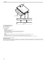
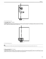
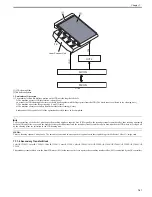
7.6.3 Detecting the Level of Toner
0014-0773
Color iR C3380G / Color iR C2880G / Color iR C3380i / Color iR C3380 / Color iR C2880i / Color iR C2880 / iR C3480 / iR C3480i / iR C3080 / iR C3080i / iR
C2550
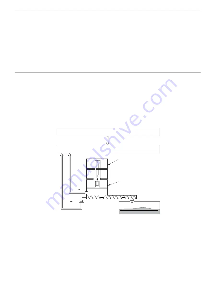
To detect the toner residual level of the hopper assembly for each color, this machine uses the following two kinds of detecting methods.
- Detection by the piezosensor
- Detection by toner refill quantity detection sensor
F-7-45
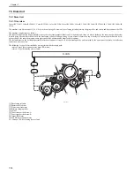
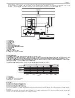
[1] Hopper assembly
[2] Toner detection signal
[3] Toner refill quantity detection signal
[4] drum unit
[5] toner container
TS1 through TS4: toner sensor (piezoelectric sensor)
PS3 to PS6: Toner feed level sensor
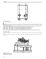
1. Detection by piezosensor
This is the detection for the presence or absence of the toner on the hopper assembly by the piezoelectric-vibrating piezosensor (TS1~4) mounted on the lower area
of the hopper assembly. It is executed at power ON, after the hopper assembly feeding and during the toner recovery control (hopper assembly forced feeding).
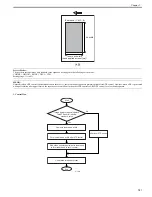
Piezosensor executes one set (sixteen times of reading) and judges the toner presence/absence based on the toner ratio at that time.
Toner absence: When the read value is judged as toner absence twelve times or more out of sixteen times
Toner presence: When judged as toner absence eight times or less out of sixteen times
The result of this detection is sent to DC control roller.
[4]
[5]
[1]
[2]
[3]
TS1 TS4
M-CON
D-CON
PS3 PS6
Содержание CiRC2550
Страница 2: ......
Страница 27: ...Chapter 1 Introduction ...
Страница 28: ......
Страница 47: ...Chapter 1 1 18 F 1 14 ON OFF ON OFF ...
Страница 70: ...Chapter 1 1 41 5 Turn on the main power switch ...
Страница 79: ...Chapter 2 Installation ...
Страница 80: ......
Страница 85: ...Chapter 2 2 3 Not available in some regions ...
Страница 134: ...Chapter 3 Basic Operation ...
Страница 135: ......
Страница 137: ......
Страница 143: ...Chapter 4 Main Controller ...
Страница 144: ......
Страница 152: ...Chapter 4 4 6 F 4 6 CPU HDD ROM access to the program at time of execution ...
Страница 171: ...Chapter 5 Original Exposure System ...
Страница 172: ......
Страница 203: ...Chapter 6 Laser Exposure ...
Страница 204: ......
Страница 206: ......
Страница 220: ...Chapter 7 Image Formation ...
Страница 221: ......
Страница 277: ...Chapter 8 Pickup Feeding System ...
Страница 278: ......
Страница 282: ......
Страница 336: ...Chapter 9 Fixing System ...
Страница 337: ......
Страница 339: ......
Страница 357: ...Chapter 10 Externals and Controls ...
Страница 358: ......
Страница 362: ......
Страница 366: ...Chapter 10 10 4 F 10 2 F 10 3 FM1 FM2 FM5 FM8 FM11 FM4 FM3 FM6 FM7 FM9 FM10 ...
Страница 375: ...Chapter 10 10 13 F 10 10 2 Remove the check mark from SNMP Status Enabled ...
Страница 376: ...Chapter 10 10 14 F 10 11 ...
Страница 402: ...Chapter 11 MEAP ...
Страница 403: ......
Страница 405: ......
Страница 452: ...Chapter 12 RDS ...
Страница 453: ......
Страница 455: ......
Страница 464: ...Chapter 13 Maintenance and Inspection ...
Страница 465: ......
Страница 467: ......
Страница 469: ...Chapter 13 13 2 F 13 1 8 9 1 2 3 3 5 6 7 10 11 12 13 14 4 ...
Страница 474: ...Chapter 14 Standards and Adjustments ...
Страница 475: ......
Страница 477: ......
Страница 485: ......
Страница 486: ...Chapter 15 Correcting Faulty Images ...
Страница 487: ......
Страница 495: ...Chapter 15 15 4 F 15 2 COLOR M 1 COLOR Y C K 0 ...
Страница 569: ...Chapter 15 15 78 F 15 82 J102 J107 J103 J108 J101 J109 J106 J112 J115 J113 J114 J104 J105 ...
Страница 570: ...Chapter 16 Self Diagnosis ...
Страница 571: ......
Страница 573: ......
Страница 600: ...Chapter 17 Service Mode ...
Страница 601: ......
Страница 603: ......
Страница 712: ...Chapter 18 Upgrading ...
Страница 713: ......
Страница 715: ......
Страница 746: ...Chapter 19 Service Tools ...
Страница 747: ......
Страница 748: ...Contents Contents 19 1 Service Tools 19 1 19 1 1 Special Tools 19 1 19 1 2 Solvents and Oils 19 2 ...
Страница 749: ......
Страница 752: ...APPENDIX ...
Страница 774: ......