


6
System 236E Installation Instructions
FACTORY DEFAULT SETTINGS
Fifteen minutes after the panel is powered up, it will dynamically test
the standby battery by interrupting AC power for two minutes and
monitoring the battery under load.
Voltage Variations
Output voltages may vary between 9 and 14.4 VDC (worst case),
depending on the load and battery condition.
If you replace the battery after a SYSTEM TROUBLE - LOW
BATTERY message, you must re-test the battery under load
conditions. Press [*] [6] [4] [#] to start the Dynamic Battery Test.
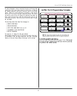
RJ-38X Wiring
Diagram
T
R
T1
R1
Incoming
Telco Line
1
2
3
4
8
7
6
5
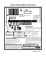
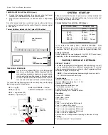
SYSTEM START-UP
T1
R1
T1 = Seized Tip
R1 = Seized
Ring
Red
Green
Protector
Ring
Tip
Tamper Jumper
House
Phones
Standby Battery Time with One LED Keypad
*Total power for all keypads and auxiliary
AUX POWER DRAIN*
6.5 A-H
Battery
4.0 A-H
Battery
32 hours
24 hours
14 hours
12 hours
24 hours
7 hours
50 mA
70 mA
150 mA
300 mA
400 mA
STANDBY TIME
DEFAULT VALUES
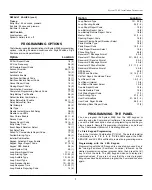
The default programming of the System 236E will allow you to use it
as a local panel without any additional programming. The actual
default programming values are shown on the Programming Work-
sheet (last 2 pages of this manual).
NOTE:
If you connect power before wiring the loops, install a
2.2K EOL resistor across each loop.
Combinations
Installer combination: 0 1 2 3 4 5
User #1 (Master) combination: 1 2 3 4
User #2 - 6: disabled
Default installer combination: yes
Combination required: no
Faulted Arming type: goof-proof
Opening/closing: O/C reports enabled
Reporting
Account #1: 000000
Dialing type: pulse
RPS allowed: yes
Zones
Zone 1 = entry/exit delay, EOL circuit
Zone 2 = interior, EOL circuit
Zone 3 = doors or windows, EOL circuit
Zone 4 = doors or windows, EOL circuit
Zone 5 = doors or windows, EOL circuit
Zone 6 = 24-hour, supervised
Panic soft zone: steady audible, reporting to Receiver #1 only
Testing
Test report interval: 7 days, disabled
2. Connect the tamper switches in series and wire the tamper
terminals to a dedicated zone of the control panel.
3. Program the dedicated zone as desired: EOL or Supervised
EOL.
Once the tamper switches are installed, opening the cabinet door
or removing the cabinet from the wall will result in a tamper signal
at the panel.
TAMPER SWITCH INSTALLATION (cont.)
Tamper Switches installed in the System 236E cabinet
TB1
LEAD-ACID
BATTERY
PRINTED CIRCUIT
BOARD
WALL
TAMPER SWITCH
DOOR
TAMPER SWITCH
TELEPHONE INTERFACE
Use an FCC compliant RJ-31X or RJ-38X plug and
jack to connect the System 236E to the phone line. The
cord requires a modular connector on one end to plug
into the wall outlet and flying leads on the other end to
connect to the panel. Wire the modular phone connec-
tor as shown in the figure at the top of the next page.
RED = ring (R)
BLUE and ORANGE = tamper
GREEN = tip (T)
YELLOW and BLACK = not used
GRAY = ring seized (R1)
BROWN = tip seized (T1)
To connect the telephone system to the control panel, use the flying
lead arrangement outlined below:


