


5
System 236E Installation Instructions
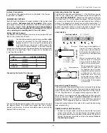
ADDRESSING KEYPADS
Each LED and Alphanumeric keypad installed in the system must
have an address.
Addresses must not be repeated
. When replac-
ing a keypad, make sure the replacement has the same address as
the previous keypad.
Once all keypads have been addressed,
reset the panel by pressing [Master Combination] [*] [6] [8] [#]
or by removing and restoring both AC and DC power
.
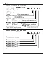
W2 W1
W2
W1
KEYPAD ADDRESS
Installed
Removed
Installed
Installed
8
9
Installed
Removed
10
Removed
Removed
11
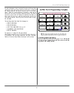
Setting Address Jumpers
The address on the LED keypad is selected by two jumpers (W1 and
W2) on the printed circuit board.
The chart below shows how to set Jumpers
W1
and
W2
to select the address for the LED keypads. Any
address from 8 to 11 can be used. The exact number
is not important, as long as each LED keypad in the
system has a different address. In the event that two
keypads are accidently given the same address, the system will fail
to respond to keypad input. Refer to page 24
for assistance in
correcting this problem.
Optional Connections:
E1 and E2 are flying leads which are only installed if the Tamper
Switch (SW1) is installed.
Connecting the Alpha Plus Keypad:
Connect the alphanumeric keypad to the control panel as shown in
the diagram above. The Alpha Plus keypad also has a jumper,
located near the piezo, that must be installed when used with the
System 236E control panel.
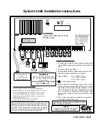
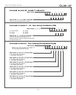
LOOP INPUTS
Terminal Labels:
Z 1 - Z 6 & C
-
+
N.C.
Alarm
EOL Loop
Each loop is individually con-
figured through program-
ming. Loops can be wired as
EOL (with a 2.2K ohm end-of-
line resistor) or as Supervised
EOL.
When programmed as EOL,
either an open or a short will
be reported as an alarm if the
system is in an armed state.
Loops 1 - 6:
0.0 - 1.5 VDC = short
1.6 - 3.1 VDC = normal
3.2 - 5.0 VDC = open
Sys
te
m
236E
Loop
Terminals
When programmed as Su-
pervised EOL, an open will
be reported as a Trouble,
whether the system is armed
or disarmed. A short on a
Supervised EOL loop will
be reported as an alarm if
the system is armed, but will
have no effect if the system
is disarmed.
+
-
Supervised Loop
N.C.
Trouble
N.O.
Alarm
Sys
te
m
236E
Loop
Terminals
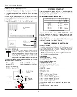
Addressing Alpha Plus Keypads
The Alpha Plus keypads use addresses 0 - 7. The first time you apply
power to the system, any unaddressed Alpha Plus keypad will
display
KEYPAD ADDRESS?
. Address each keyupad by pressing
a number from 0 to 7 at the respective keypad. The exact number
you press is not important, as long as each keypad has a different
address. The keypad will not accept any address greater than 7. If
you hsould accidentally use the same address for more than one
keypad, the system will fail to properly respond to keypad input.
Refer to page 26 for assistance in correcting this problem.
Keyswitch Arming/Disarming
The System 236E is capable of being armed or disarmed by installing
a keyswitch on the Zone 6 input. Only a maintained switch may be
used. The loop must be programmed for keyswitch arming (see CL
1D - 22, Digit Position 4). Keyswitch Arming reports as User #7.
When Zone 6 is programmed for Keyswitch Arming, the only valid
switch positions are:
Open = System is Disarmed
, and
Closed =
System is Armed
. Use C & K Model Y101132V203NQ or equivalent
switchlock. This configuration does not require an EOL resistor.
Keyswitch arming follows all the rules of the panel's faulted arming
type programming.
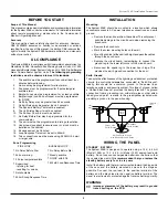
TAMPER SWITCH INSTALLATION
1. Position the tamper switch inside the cabinet at the lower right
corner of the cabinet. For the wall tamper, the plunger should
go through the small hole in the back of the cabinet. For the door
tamper, the plunger should face out from the cabinet.
Refer to
the drawing on page 6
.


