


3
System 236E Installation Instructions
Mounting
The System 236E should be mounted in a location which allows
convenient access to AC power, telephone connections, and earth
ground.
Remove the circuit board from the cabinet. This will prevent
possible damage to the circuit board when removing the
knock-outs.
Remove the knock-outs.
Mark the screw mounting holes on the wall.
Mount the cabinet at the desired height and pass the cables
through the knock-outs.
Replace the circuit board, remembering to connect the
ground lug to the lower left corner of the circuit board.
Reconnect the spade lug to the lower door hinge. This
provides the earth ground connection for the door.
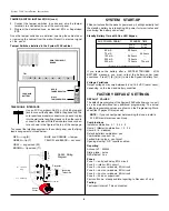
INSTALLATION
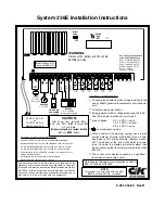
Zone Programming
FIRE LOOP
BURGLAR LOOP
•
No Delay Before Dial
•
24-hour arming
•
3 Pulse temporal audible
•
Supervised
- latching for heat
- resetting for smoke
•
Not shuntable
•
500mS Loop Response Time
•
No Delay Before Dial
•
Steady audible
•
NO/NC with EOL
•
500mS Loop Response Time
BEFORE YOU START
Scope of This Manual
This manual contains basic installation and programming information
for the System 236E control/communicator. For detailed information
about remote programming, please refer to the Commander II/
Monitor II Operating Manual.
Accuracy
This manual has been carefully checked for accuracy. However,
C&K SYSTEMS assumes no liability for inaccuracies or actions
resulting from the use of this manual. In addition, C&K reserves the
right to modify the System 236E hardware, software, and manuals
without prior notice.
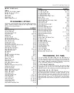
UL COMPLIANCE
The System 236E is in compliance with Underwriters Laboratories, Inc.
Standards UL 985, Household Fire Warning System Units; UL 1023,
Household Burglar Alarm System Units; and UL 1635, Digital Burglar
Alarm Communicator System Units.
The following programming
restrictions must be observed to meet UL standards:
1.
The audible must be programmed to sound at least four
minutes before silencing.
2.
No zone may be programmed for silent alarm.
3.
Fire zones must be programmed for 3 pulse temporal
audible alarm.
4.
Burglar zones must be programmed for a steady audible.
5.
Burglar loops (non-24-hour loops) must be programmed
for NO/NC.
6.
No Entry Delay may be greater than 45 seconds.
7.
No Exit Delay may be greater than 60 seconds.
8.
The Dynamic Battery Test must be enabled.
9.
The Unit Status Report must be enabled.
10. The 24-hour Check-in must be enabled.
11. No Delay Before Dial may be programmed for the
communicator.
12. The unit must not be programmed to dial a police station.
13. Use screws (supplied) to secure cover or a lock must be
installed on the cabinet.
14. All devices must be UL listed.
15. Loop Response Time must be set to 500mS.
16. Telco connections must be made using 26 AWG (0.4 mm)
or larger wire.
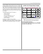
Power
Lines
Control
Panel
Unified Earth Ground
with Bonded Ground Roots
Telephone
Earth Ground
Power Line
Earth Ground
Telephone
Lines
Earth Ground
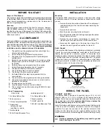
To ensure the effectiveness of the lightning and transient protection
circuits, the control panel
must
be connected to "Earth Ground".
Ideally, this should be a common ground to the power lines,
telephone system, and security system. This type of ground, called
a "Unified Earth Ground", provides the best protection. The ground
connection, from a grounding rod, cold water pipe or other estab-
lished ground point, is made to the green/yellow jacketed wire,
providing a ground to the panel housing.
WIRING THE PANEL
STANDBY BATTERY
The System 236E is designed to operate using a 12 V, 6.5 A-H
(Model 1265) or 12 V, 4.0 A-H (Model 1240) sealed lead-acid
battery. Do not use non-rechargeable batteries or batteries other
than sealed lead-acid.
It is recommended that you replace the
standby battery every four to six years
.
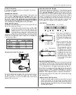
Install the battery with the terminals oriented toward the hinge side
of the case and the battery mounted as close to the hinge as
possible. Connect the red lead to the positive terminal of the
battery and the black lead to the negative battery terminal. The
panel is electronically protected against reverse battery polarity.
Improper placement of the battery may result in ground
trace shorting on the PCB.
WARNING:


