

Chapter 7: Operation
Spectrum management
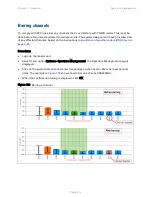
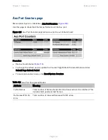
Key metrics
The “I” bar and top of the colored bar represent three key metrics (
). The vertical part of
the “I” bar represents the statistical spread between the peak and the mean of the statistical
distribution.
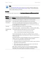
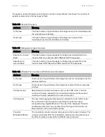
Table 106 Key metrics represented in the spectrum management plot
Metric
Description
How represented
Peak of Means
The largest mean interference measurement
encountered during the quantization period. The
peak of means is useful for detecting slightly
longer duration spikes in the interference
environment.
Upper horizontal
bar.
Mean of Means
The arithmetic mean of the measured means
during a quantization period. The mean of means
is a coarse measure of signal interference and
gives an indication of the average interference
level measured during the quantization period.
The metric is not very good at predicting
intermittent interference and is included to show
the spread between the Mean of Means, the
99.9% Percentile and the Peak of Means.
Lower horizontal
bar.
99.9% Percentile
of the Means
The value of mean interference measurement
which 99.9% of all mean measurements fall
below, during the quantization period. The 99.9%
percentile metric is useful for detecting short
duration repetitive interference that by its very
nature has a minimal effect of the mean of means.
Top of the colored
bar.
Note
The arithmetic mean is the true power mean and not the mean of the values expressed
in dBm.
Spectrum Management uses the 99.9% Percentile as the prime interference
measurement. All subsequent references to interference level refer to this percentile
measurement.
Page
7-25
Содержание PTP 650 Series
Страница 1: ...Cambium PTP 650 Series User Guide System Release 650 01 01 ...
Страница 88: ...Chapter 3 System planning Typical deployment Figure 24 Wall installation Page 3 3 ...
Страница 89: ...Chapter 3 System planning Typical deployment Figure 25 Roof installation Page 3 4 ...
Страница 91: ...Chapter 3 System planning Typical deployment Figure 27 ODU with optical SFP and PSU interfaces Page 3 6 ...
Страница 92: ...Chapter 3 System planning Typical deployment Figure 28 ODU with Aux and PSU interfaces Page 3 7 ...
Страница 264: ...Chapter 6 Configuration and alignment System menu Figure 69 QoS Configuration page IP MPLS Page 6 31 ...
Страница 289: ...Chapter 6 Configuration and alignment Management menu Figure 82 Time Configuration page SNTP enabled Page 6 56 ...