


Chapter 3: System planning
Link planning
LoS links in radar regions
When planning an LoS link to operate in a radar detection region, ensure that receiver signal level
is low enough to allow the PTP 650 to detect radar signals:
•
With integrated antennas, the recommended minimum LoS operating range is 110 meters
(360 ft) for 5.4 GHz or 185 meters (610 ft) for 5.8 GHz. Shorter operating ranges will lead to
excessive receiver signal levels.
•
With higher gain connectorized antennas, ensure the predicted receiver signal level (from
LINKPlanner) is below -53 dBm (for 5.4 GHz) or below -58 dBm (for 5.8 GHz).
Path loss
Path loss is the amount of attenuation the radio signal undergoes between the two ends of the
link. The path loss is the sum of the attenuation of the path if there were no obstacles in the way
(Free Space Path Loss), the attenuation caused by obstacles (Excess Path Loss) and a margin to
allow for possible fading of the radio signal (Fade Margin). The following calculation needs to be
performed to judge whether a particular link can be installed:
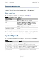
capability
seasonal
fade
excess
space
free
L
L
L
L
L
<
+
+
+
_
Where:
Is:
space
free
L
_
Free Space Path Loss (dB)
excess
L
Excess Path Loss (dB)
fade
L
Fade Margin Required (dB)
seasonal
L
Seasonal Fading (dB)
capability
L
Equipment Capability (dB)
Adaptive modulation
Adaptive modulation ensures that the highest throughput that can be achieved instantaneously
will be obtained, taking account of propagation and interference. When the link has been installed,
web pages provide information about the link loss currently measured by the equipment, both
instantaneously and averaged. The averaged value will require maximum seasonal fading to be
added, and then the radio reliability of the link can be computed. For minimum error rates on TDM
links, the maximum modulation mode should be limited to 64QAM 0.75.
For details of the system threshold, output power and link loss for each frequency band in all
modulation modes for all available channel bandwidths, refer to
System threshold, output power
Page
3-22
Содержание PTP 650 Series
Страница 1: ...Cambium PTP 650 Series User Guide System Release 650 01 01 ...
Страница 88: ...Chapter 3 System planning Typical deployment Figure 24 Wall installation Page 3 3 ...
Страница 89: ...Chapter 3 System planning Typical deployment Figure 25 Roof installation Page 3 4 ...
Страница 91: ...Chapter 3 System planning Typical deployment Figure 27 ODU with optical SFP and PSU interfaces Page 3 6 ...
Страница 92: ...Chapter 3 System planning Typical deployment Figure 28 ODU with Aux and PSU interfaces Page 3 7 ...
Страница 264: ...Chapter 6 Configuration and alignment System menu Figure 69 QoS Configuration page IP MPLS Page 6 31 ...
Страница 289: ...Chapter 6 Configuration and alignment Management menu Figure 82 Time Configuration page SNTP enabled Page 6 56 ...


