


Chapter 3: System planning
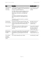
System threshold, output power and link loss
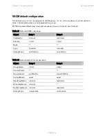
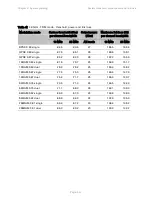
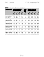
Table 44 5.8 GHz - IP mode - threshold, power and link loss
Modulation mode
System threshold (dBm)
per channel bandwidth
Output
power
(dBm)
Maximum link loss (dB)
per channel bandwidth
10
MHz
20
MHz
40
MHz
45
MHz
All
bands
10
MHz
20
MHz
40
MHz
45
MHz
BPSK 0.63 single
-95.8 -92.9 -89.6 -89.4
27
168.8 165.9 162.6
162.4
QPSK 0.63 single
-90.3 -87.9 -85.3 -85.0
26
163.3 160.9 158.3
158.0
QPSK 0.87 single
-87.3 -84.5 -81.4 -81.0
26
160.3 157.5 154.4
154.0
16QAM 0.63 single
-85.2 -82.5 -79.2 -78.9
25
157.2 154.5 151.2
150.9
16QAM 0.63 dual
-81.4 -79.0 -75.7 -75.3
25
153.4 151.0 147.7
147.3
16QAM 0.87 single
-80.6 -77.8 -74.8 -74.6
25
152.6 149.8 146.8
146.6
16QAM 0.87 dual
-77.3 -74.4 -71.4 -71.1
25
149.3 146.4 143.4
143.1
64QAM 0.75 single
-77.3 -74.8 -71.7 -71.4
24
148.3 145.8 142.7
142.4
64QAM 0.75 dual
-74.5 -71.5 -68.5 -68.2
24
145.5 142.5 139.5
139.2
64QAM 0.92 single
-73.4 -70.7 -67.7 -67.5
24
144.4 141.7 138.7
138.5
64 QAM 0.92 dual
-70.0 -67.1 -64.2 -64.0
24
141.0 138.1 135.2
135.0
256QAM 0.81 single -70.1 -67.4 -64.8 -64.4
23
139.1 136.4 133.8
133.4
256QAM 0.81 dual
-67.0 -64.0 -61.2 -60.8
23
136.0 133.0 130.2
129.8
Page
3-45
Содержание PTP 650 Series
Страница 1: ...Cambium PTP 650 Series User Guide System Release 650 01 01 ...
Страница 88: ...Chapter 3 System planning Typical deployment Figure 24 Wall installation Page 3 3 ...
Страница 89: ...Chapter 3 System planning Typical deployment Figure 25 Roof installation Page 3 4 ...
Страница 91: ...Chapter 3 System planning Typical deployment Figure 27 ODU with optical SFP and PSU interfaces Page 3 6 ...
Страница 92: ...Chapter 3 System planning Typical deployment Figure 28 ODU with Aux and PSU interfaces Page 3 7 ...
Страница 264: ...Chapter 6 Configuration and alignment System menu Figure 69 QoS Configuration page IP MPLS Page 6 31 ...
Страница 289: ...Chapter 6 Configuration and alignment Management menu Figure 82 Time Configuration page SNTP enabled Page 6 56 ...


