


Chapter 7: Operation
Spectrum management
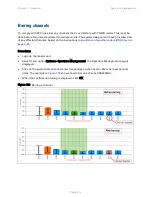
X axis and Y axis
The X-axis shows a stylized view of the selectable wireless channels. Adjacent channels on the
display have a 10 MHz overlap. Channels are displayed separately for clarity. The axis is labeled
using the channel center frequencies in MHz.
The Y-axis shows the interference power levels from –100 to –40 dBm.
Channel states
The active channel (channel 5 in
) is always marked using hatched green and white
lines. The width of the hatching is directly proportional the channel bandwidth spectral occupancy
of the channel.
The individual channel metrics are displayed using a colored bar and an “I” bar. The colored bar
represents the channel state (
Table 105 Channel states represented in the spectrum management plot
Color
State
Meaning
Green
Active
The channel is currently in use, hosting the Point-to-Point
wireless link.
Orange
Interference
The channel has interference above the interference
threshold.
Blue
Available
The channel has an interference level below the
interference threshold and is considered by the Spectrum
Management algorithm suitable for hosting the
Point-to-Point link.
Grey
Barred
The system administrator has barred this channel from use.
For improved visibility, an additional red “lock” symbol is
used to indicate that a channel is barred.
Page
7-24
Содержание PTP 650 Series
Страница 1: ...Cambium PTP 650 Series User Guide System Release 650 01 01 ...
Страница 88: ...Chapter 3 System planning Typical deployment Figure 24 Wall installation Page 3 3 ...
Страница 89: ...Chapter 3 System planning Typical deployment Figure 25 Roof installation Page 3 4 ...
Страница 91: ...Chapter 3 System planning Typical deployment Figure 27 ODU with optical SFP and PSU interfaces Page 3 6 ...
Страница 92: ...Chapter 3 System planning Typical deployment Figure 28 ODU with Aux and PSU interfaces Page 3 7 ...
Страница 264: ...Chapter 6 Configuration and alignment System menu Figure 69 QoS Configuration page IP MPLS Page 6 31 ...
Страница 289: ...Chapter 6 Configuration and alignment Management menu Figure 82 Time Configuration page SNTP enabled Page 6 56 ...


