Chapter 1: Product description
Ethernet bridging
Customer data network
Transparent Ethernet service
The PTP 650 Series provides an Ethernet service between one of the Ethernet ports at a local ODU
and one of the Ethernet ports at an associated remote ODU. The Ethernet service is based on
conventional layer two transparent bridging, and is equivalent to the Ethernet Private Line (EPL)
service defined by the Metro Ethernet Forum (MEF).
The service is transparent to untagged frames, standard VLAN frames, priority-tagged frames,
provider bridged frames, Q-in-Q frames and provider backbone bridged frames. In each case, the
service preserves MAC addresses, VLAN ID, Ethernet priority and Ethernet payload in the
forwarded frame. The maximum frame size for bridged frames in the customer network is
9600 bytes.
Note
There is no requirement for the customer data network to be connected to the same
Ethernet port at both ends of a wireless link. For example, it is possible to connect the
Main PSU port to the customer data network at one end of the link and to connect the
Aux port to the customer data network at the other end of the link.
Layer two control protocols
The PTP 650 Series is transparent to layer two control protocols (L2CP) including:
•
Spanning tree protocol (STP), rapid spanning tree protocol (RSTP)
•
Multiple spanning tree protocol (MSTP)
•
Link aggregation control protocol (LACP)
•
Link OAM, IEEE 802.3ah
•
Port authentication, IEEE 802.1X
•
Ethernet local management interface (E-LMI), ITU-T Q.933.
•
Link layer discovery protocol (LLDP)
•
Multiple registration protocol (MRP)
•
Generic attribute registration protocol (GARP)
The PTP 650 Series does not generate or respond to any L2CP traffic.
Page
1-16
Содержание PTP 650 Series
Страница 1: ...Cambium PTP 650 Series User Guide System Release 650 01 01 ...
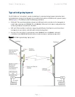
Страница 88: ...Chapter 3 System planning Typical deployment Figure 24 Wall installation Page 3 3 ...
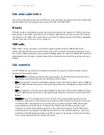
Страница 89: ...Chapter 3 System planning Typical deployment Figure 25 Roof installation Page 3 4 ...
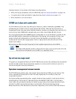
Страница 91: ...Chapter 3 System planning Typical deployment Figure 27 ODU with optical SFP and PSU interfaces Page 3 6 ...
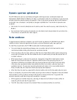
Страница 92: ...Chapter 3 System planning Typical deployment Figure 28 ODU with Aux and PSU interfaces Page 3 7 ...
Страница 264: ...Chapter 6 Configuration and alignment System menu Figure 69 QoS Configuration page IP MPLS Page 6 31 ...
Страница 289: ...Chapter 6 Configuration and alignment Management menu Figure 82 Time Configuration page SNTP enabled Page 6 56 ...


