


Chapter 1: Product description
Overview of the PTP 650
Hardware overview
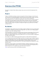
The main hardware components of the PTP 650 are as follows:
•
Outdoor unit (ODU): The ODU is a self-contained transceiver unit that houses both radio and
networking electronics. The ODU is supplied in the following product variants:
o
Integrated or Connectorized: The ODU may be either Integrated (attached to its own flat
plate antenna) or connectorized (without an antenna).
o
FCC/IC, EU or RoW: These variants are for deployment in the USA and Canada, the EU and
the rest of the world respectively.
•
Power supply unit (PSU): There is a choice of two PSUs:
o
The AC Power Injector is suitable for installations without an auxiliary device.
o
The AC+DC power injector is required when powering from a DC supply or when the PSU
is needed to operate at extreme temperatures.
•
Antennas and antenna cabling: Connectorized ODUs require external antennas connected
using RF cable.
•
Ethernet cabling: All configurations require a copper Ethernet Cat5e connection from the ODU
(PSU port) to the PSU. Advanced configurations may also require one or both of the following:
o
A copper or optical Ethernet connection from the ODU (SFP port) to network terminating
equipment or another device.
o
A copper Ethernet Cat5e connection from the ODU (Aux port) to an auxiliary device.
•
Lightning protection unit (LPU): LPUs are installed in the PSU and Aux copper drop cables to
provide transient voltage surge suppression.
•
Ground cables: ODU, LPUs and outdoor copper Ethernet cables are bonded to the site
grounding system using ground cables.
For more information about these components, including interfaces, specifications and Cambium
part numbers, refer to
Page
1-5
Содержание PTP 650 Series
Страница 1: ...Cambium PTP 650 Series User Guide System Release 650 01 01 ...
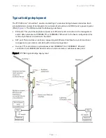
Страница 88: ...Chapter 3 System planning Typical deployment Figure 24 Wall installation Page 3 3 ...
Страница 89: ...Chapter 3 System planning Typical deployment Figure 25 Roof installation Page 3 4 ...
Страница 91: ...Chapter 3 System planning Typical deployment Figure 27 ODU with optical SFP and PSU interfaces Page 3 6 ...
Страница 92: ...Chapter 3 System planning Typical deployment Figure 28 ODU with Aux and PSU interfaces Page 3 7 ...
Страница 264: ...Chapter 6 Configuration and alignment System menu Figure 69 QoS Configuration page IP MPLS Page 6 31 ...
Страница 289: ...Chapter 6 Configuration and alignment Management menu Figure 82 Time Configuration page SNTP enabled Page 6 56 ...


