


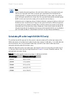
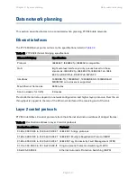


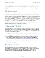
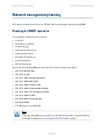


Chapter 3: System planning
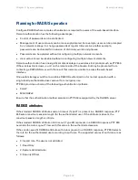
Planning for connectorized units
Planning for connectorized units
This section describes factors to be taken into account when planning to use connectorized ODUs
with external antennas in PTP 650 links.
When to install connectorized units
The majority of radio links can be successfully deployed with the integrated ODU. However the
integrated units may not be sufficient in some areas, for example:
•
Where the path is heavily obscured by dense woodland on an NLOS link.
•
Where long LOS links (>23 km or >14 miles) are required.
•
Where there are known to be high levels of interference.
PTP LINKPlanner can be used to identify these areas of marginal performance.
In these areas, connectorized ODUs and external antennas should be used.
Choosing external antennas
When selecting external antennas, consider the following factors:
•
The required antenna gain.
•
Ease of mounting and alignment.
•
Antenna polarization:
o
For a simple installation process, select one dual-polarization antenna (as the integrated
antenna) at each end.
o
To achieve spatial diversity, select two single-polarization antennas at each end. Spatial
diversity provides additional fade margin on very long LOS links where there is evidence of
correlation of the fading characteristics on Vertical and Horizontal polarizations.
Note
Enter the antenna gain and cable loss into the Installation Wizard, if the country
selected has an EIRP limit, the corresponding maximum transmit power will be
calculated automatically by the unit.
Page
3-25
Содержание PTP 650 Series
Страница 1: ...Cambium PTP 650 Series User Guide System Release 650 01 01 ...
Страница 88: ...Chapter 3 System planning Typical deployment Figure 24 Wall installation Page 3 3 ...
Страница 89: ...Chapter 3 System planning Typical deployment Figure 25 Roof installation Page 3 4 ...
Страница 91: ...Chapter 3 System planning Typical deployment Figure 27 ODU with optical SFP and PSU interfaces Page 3 6 ...
Страница 92: ...Chapter 3 System planning Typical deployment Figure 28 ODU with Aux and PSU interfaces Page 3 7 ...
Страница 264: ...Chapter 6 Configuration and alignment System menu Figure 69 QoS Configuration page IP MPLS Page 6 31 ...
Страница 289: ...Chapter 6 Configuration and alignment Management menu Figure 82 Time Configuration page SNTP enabled Page 6 56 ...


