VI-9
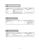
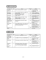
I-11 Dropout
Possible cause
Step
Check
Result
Remedy
Paper failure
1
Is recommended paper used?
No
Use recommended paper.
Paper soaked
2
Is paper soaked?
Yes
Store the paper in packing
paper to keep it from
soaking.
EP-ED HC
cartridge
3
Does printed image improve when the EP-ED
HC cartridge is replaced?
Yes
Replace the EP-ED HC
cartridge.
Transfer roller
failure
4
Is there any dirt on the transfer roller or is it
deformed?
Yes
Clean or replace the
transfer roller assy.
Transfer input
signal error
5
Do the pins 7 and 8 of the connector
P6 on the main PCB have the following value
respectively when a sheet of paper is fed from
the MP tray?
P6-7 pin (HVT2) --- Change in voltage from
15V approx. to 0V about 1 second after a
sheet of paper is fed.
P6-8 pin (HVT3) --- Change in voltage from
9V approx. to 0V when the voltage at the
pin 7 changes from 0V to 15V.
No
Replace the main PCB
assy or the harness.
Dirt on power
supply terminal
6
Clean the transfer roller right end bearing, the
check continuity between the transfer roller
power supply spring and the terminal of the
No
Clean the contact to
assure the continuity.
Failure in the
transfer high-
voltage circuit
high-voltage transfer unit. Is there continuity?
Yes
Replace the high-voltage
power supply PCB assy.
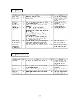
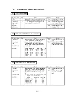
I-12 White vertical streaks
Possible cause
Step
Check
Result
Remedy
Toner bias
1
Do white vertical stripes appear like a band?
Yes
Rock the cartridge, set it
again in the printer and
check again the print
quality.
Drum damage
2
Does print quality improve when the EP-ED
HC cartridge is replaced?
Yes
Replace the EP-ED HC
cartridge.
Transfer roller
failure
3
Is the transfer roller damaged or deformed?
Yes
Replace the transfer roller
assy.
Dirt on the
reflecting mirror
4
Is the problem solved when the laser unit is
replaced?
Yes
Clean the reflecting mirror
with a cleaning tip or
replace the laser unit.
Содержание HL-2060
Страница 1: ...MECHANICS ELECTRONICS SERVICE MANUAL LASER PRINTER ...
Страница 41: ...III 8 A B F C D E 1 E 2 E 3 E 4 E 5 F Figure 3 7 Paper Feed Size SW PCB Circuit ...
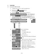
Страница 129: ...VII 16 Test for memory MEMORY DISPLAY MEMORY DEBUG MEMORY TEST exit MENU ...
Страница 136: ...Appendix A 2 Paper Feed Size SW PCB Circuitry Diagram 1 1 CODE UK4067000 B512011 012 CIR NAME A 2 ...
Страница 137: ...Appendix A 3 Main PCB Circuitry Diagram 1 7 CODE UK4058000 B512006 CIR 1 7 NAME A 3 ...
Страница 138: ...Appendix A 4 Main PCB Circuitry Diagram 2 7 CODE UK4058000 B512006 CIR 2 7 NAME A 4 ...
Страница 139: ...Appendix A 5 Main PCB Circuitry Diagram 3 7 CODE UK4058000 B512006 CIR 3 7 NAME A 5 ...
Страница 140: ...Appendix A 6 Main PCB Circuitry Diagram 4 7 CODE UK4058000 B512006 CIR 4 7 NAME A 6 ...
Страница 141: ...Appendix A 7 Main PCB Circuitry Diagram 5 7 CODE UK4058000 B512006 CIR 5 7 NAME A 7 ...
Страница 142: ...Appendix A 8 Main PCB Circuitry Diagram 6 7 CODE UK4058000 B512006 CIR 6 7 NAME A 8 ...
Страница 143: ...Appendix A 9 Main PCB Circuitry Diagram 7 7 CODE UK4058000 B512006 CIR 7 7 NAME A 9 ...
Страница 144: ...Appendix A 10 Control Panel PCB Circuitry Diagram 1 1 CODE UK4077000 B512005 CIR NAME A 10 ...
Страница 145: ...Appendix A 11 Laser LD PCB Circuitry Diagram 1 1 CODE UK3253000 B48K253 CIR NAME A 11 ...
Страница 147: ...June 98 54T046NE0 HL2060 ...


