IV-18
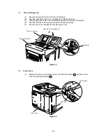
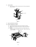
1.20 Roller
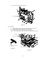
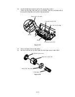
Holder
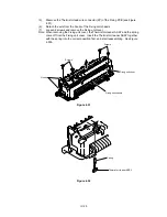
(1)
Remove the Gear 28.
(2)
Loosen and pull out the 2 screws.
Figure 4.35
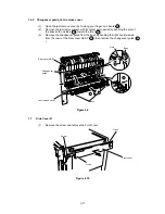
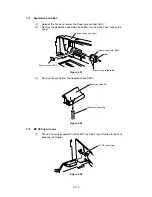
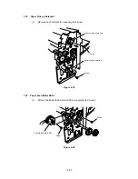
1.21
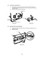
Paper pick-up roller ASSY, Bearing
(1)
Pull out the MP paper pick-up gear 35 and the Tray paper pick-up gear 35, from
the Paper pick-up roller shafts.
Figure 4.36
Bearings
MP paper pick-up gear 35
Paper pick-up roller shafts
Tray paper pick-up gear 35
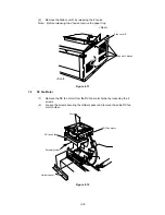
Gear 28
Roller holder
Screws
Содержание HL-2060
Страница 1: ...MECHANICS ELECTRONICS SERVICE MANUAL LASER PRINTER ...
Страница 41: ...III 8 A B F C D E 1 E 2 E 3 E 4 E 5 F Figure 3 7 Paper Feed Size SW PCB Circuit ...
Страница 129: ...VII 16 Test for memory MEMORY DISPLAY MEMORY DEBUG MEMORY TEST exit MENU ...
Страница 136: ...Appendix A 2 Paper Feed Size SW PCB Circuitry Diagram 1 1 CODE UK4067000 B512011 012 CIR NAME A 2 ...
Страница 137: ...Appendix A 3 Main PCB Circuitry Diagram 1 7 CODE UK4058000 B512006 CIR 1 7 NAME A 3 ...
Страница 138: ...Appendix A 4 Main PCB Circuitry Diagram 2 7 CODE UK4058000 B512006 CIR 2 7 NAME A 4 ...
Страница 139: ...Appendix A 5 Main PCB Circuitry Diagram 3 7 CODE UK4058000 B512006 CIR 3 7 NAME A 5 ...
Страница 140: ...Appendix A 6 Main PCB Circuitry Diagram 4 7 CODE UK4058000 B512006 CIR 4 7 NAME A 6 ...
Страница 141: ...Appendix A 7 Main PCB Circuitry Diagram 5 7 CODE UK4058000 B512006 CIR 5 7 NAME A 7 ...
Страница 142: ...Appendix A 8 Main PCB Circuitry Diagram 6 7 CODE UK4058000 B512006 CIR 6 7 NAME A 8 ...
Страница 143: ...Appendix A 9 Main PCB Circuitry Diagram 7 7 CODE UK4058000 B512006 CIR 7 7 NAME A 9 ...
Страница 144: ...Appendix A 10 Control Panel PCB Circuitry Diagram 1 1 CODE UK4077000 B512005 CIR NAME A 10 ...
Страница 145: ...Appendix A 11 Laser LD PCB Circuitry Diagram 1 1 CODE UK3253000 B48K253 CIR NAME A 11 ...
Страница 147: ...June 98 54T046NE0 HL2060 ...

