II-4
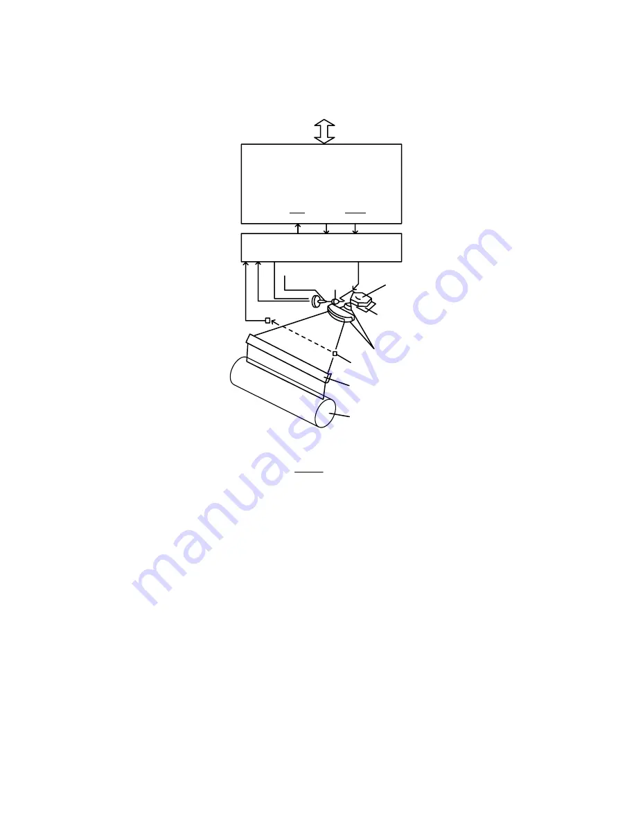
2. LASER
SYSTEM
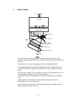
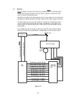
Laser unit driver
Collimator lens
Cylindrical lens
Laser unit motor
Scanning mirror
Focusing lenses
Beam detect mirror
Reflective mirror
Photosensitive drum
Optical sensor
To external device
Main PCB
SBD
DATA VOFF
Figure 2.4
In response to the print signal transmitted from the external device, the main PCB
generates the drive signals (DATA,VOFF) for the laser diode and sends the signals to the
laser unit.
The laser diode in the laser unit generates a laser beam modulated by DATA.
The modulated laser beam is aligned into a parallel beam by a collimator lens and a
cylindrical lens and then brought to the scanning mirror which is rotating at a constant
speed.
The laser beam reflected by the scanning mirror focuses on the photosensitive drum via
the focusing lenses arranged in front of the scanning mirror.
The path of the beam coming through the focusing lenses is reflected by the reflective
mirror.
As the scanning mirror rotates at a constant speed, the laser beam scans the
photosensitive drum at a constant speed.
As the photosensitive drum rotates at a constant speed and the laser beam scans the
drum, an images is formed on the drum.
Содержание HL-2060
Страница 1: ...MECHANICS ELECTRONICS SERVICE MANUAL LASER PRINTER ...
Страница 41: ...III 8 A B F C D E 1 E 2 E 3 E 4 E 5 F Figure 3 7 Paper Feed Size SW PCB Circuit ...
Страница 129: ...VII 16 Test for memory MEMORY DISPLAY MEMORY DEBUG MEMORY TEST exit MENU ...
Страница 136: ...Appendix A 2 Paper Feed Size SW PCB Circuitry Diagram 1 1 CODE UK4067000 B512011 012 CIR NAME A 2 ...
Страница 137: ...Appendix A 3 Main PCB Circuitry Diagram 1 7 CODE UK4058000 B512006 CIR 1 7 NAME A 3 ...
Страница 138: ...Appendix A 4 Main PCB Circuitry Diagram 2 7 CODE UK4058000 B512006 CIR 2 7 NAME A 4 ...
Страница 139: ...Appendix A 5 Main PCB Circuitry Diagram 3 7 CODE UK4058000 B512006 CIR 3 7 NAME A 5 ...
Страница 140: ...Appendix A 6 Main PCB Circuitry Diagram 4 7 CODE UK4058000 B512006 CIR 4 7 NAME A 6 ...
Страница 141: ...Appendix A 7 Main PCB Circuitry Diagram 5 7 CODE UK4058000 B512006 CIR 5 7 NAME A 7 ...
Страница 142: ...Appendix A 8 Main PCB Circuitry Diagram 6 7 CODE UK4058000 B512006 CIR 6 7 NAME A 8 ...
Страница 143: ...Appendix A 9 Main PCB Circuitry Diagram 7 7 CODE UK4058000 B512006 CIR 7 7 NAME A 9 ...
Страница 144: ...Appendix A 10 Control Panel PCB Circuitry Diagram 1 1 CODE UK4077000 B512005 CIR NAME A 10 ...
Страница 145: ...Appendix A 11 Laser LD PCB Circuitry Diagram 1 1 CODE UK3253000 B48K253 CIR NAME A 11 ...
Страница 147: ...June 98 54T046NE0 HL2060 ...


