VI-26
7.
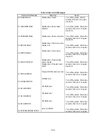
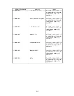
STATUS MESSAGE LIST
Table 6.2 Operator Call Messages
Operator Call Message
Meaning
Action
CHECK XX TRAY
12 COVER OPEN
13 JAM XXXXXX
14 NO CARTRIDGE
XX NO CASSETTE
16 TONER EMPTY
XX LOAD PAPER ***** SIZE
18 MANUAL FEED ***** SIZE
19 CHECK FONT
20 FONT REMOVAL 1
FONT REMOVAL 2
27 NO DX UNIT
27 NO DX TRAY
27 DX OPEN
The paper cassette (XX is
MP/T1/T2) is out of paper.
The upper cover of the printer
is open.
Paper is jammed in the printer.
XXXXXX is
TRAYS/INSIDE/REAR/DUPLEX.
The toner cartridge is not
installed in the printer.
The paper cassette is not
installed. XX is T1/T2.
The printer has almost run out
of toner: you may print another
30 to 100 pages. (The ALARM
lamp lights at the same time.)
The wrong size of paper was
loaded in the paper cassette
XX. XX is MP/ T1/T2. (The
message appears alternately
to show a particular size.)
The printer requests you to
load paper manually. (The
message appears alternately
to show a particular size.)
An error occurred in the
optional font cartridge/card.
The font card was removed
while the printer is on-line.
The duplex unit is not installed
with the printer when the
duplex printing mode is
selected.
The duplex paper guide tray is
not installed in T1 when the
duplex printing mode is
selected.
The cover of the duplex unit is
open.
Load a stack of paper into the
cassette. See M-7.
Close the cover. See M-6.
Remove the jammed paper
from the indicated area.
See M-10.
Install a toner cartridge.
See M-8.
Install the paper cassette.
Remove the toner cartridge,
rock it several times at 45
°
,
and install it again. Or replace
the toner cartridge with a new
one. See M-9.
Load the requested size of
paper in the paper cassette, or
load it on the manual feed tray
and press the FORM FEED
switch.
Load the requested size of
paper on the multi-purpose
tray and press the SEL switch.
Turn off the printer, and
reinstall or replace the optional
font cartridge/card.
Turn off the printer, install the
font card, and turn on the
printer. The CONTINUE switch
will allow you to temporarily
ignore this message.
Install the duplex unit
correctly. See the DX-1200
user’s guide.
Install the duplex paper guide
tray into T1. See the DX-2000
user’s guide.
Close the cover. See the DX-
2000 user’s guide.
Содержание HL-2060
Страница 1: ...MECHANICS ELECTRONICS SERVICE MANUAL LASER PRINTER ...
Страница 41: ...III 8 A B F C D E 1 E 2 E 3 E 4 E 5 F Figure 3 7 Paper Feed Size SW PCB Circuit ...
Страница 129: ...VII 16 Test for memory MEMORY DISPLAY MEMORY DEBUG MEMORY TEST exit MENU ...
Страница 136: ...Appendix A 2 Paper Feed Size SW PCB Circuitry Diagram 1 1 CODE UK4067000 B512011 012 CIR NAME A 2 ...
Страница 137: ...Appendix A 3 Main PCB Circuitry Diagram 1 7 CODE UK4058000 B512006 CIR 1 7 NAME A 3 ...
Страница 138: ...Appendix A 4 Main PCB Circuitry Diagram 2 7 CODE UK4058000 B512006 CIR 2 7 NAME A 4 ...
Страница 139: ...Appendix A 5 Main PCB Circuitry Diagram 3 7 CODE UK4058000 B512006 CIR 3 7 NAME A 5 ...
Страница 140: ...Appendix A 6 Main PCB Circuitry Diagram 4 7 CODE UK4058000 B512006 CIR 4 7 NAME A 6 ...
Страница 141: ...Appendix A 7 Main PCB Circuitry Diagram 5 7 CODE UK4058000 B512006 CIR 5 7 NAME A 7 ...
Страница 142: ...Appendix A 8 Main PCB Circuitry Diagram 6 7 CODE UK4058000 B512006 CIR 6 7 NAME A 8 ...
Страница 143: ...Appendix A 9 Main PCB Circuitry Diagram 7 7 CODE UK4058000 B512006 CIR 7 7 NAME A 9 ...
Страница 144: ...Appendix A 10 Control Panel PCB Circuitry Diagram 1 1 CODE UK4077000 B512005 CIR NAME A 10 ...
Страница 145: ...Appendix A 11 Laser LD PCB Circuitry Diagram 1 1 CODE UK3253000 B48K253 CIR NAME A 11 ...
Страница 147: ...June 98 54T046NE0 HL2060 ...

