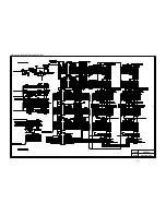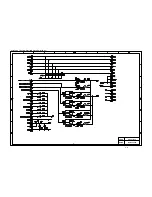
background image

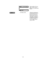
VII-17

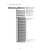
  1.3

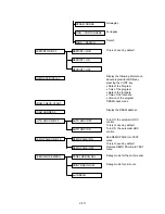
Off-line and Hold Down CONT + SEL Keys

Display

Selection

Discription
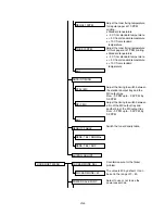
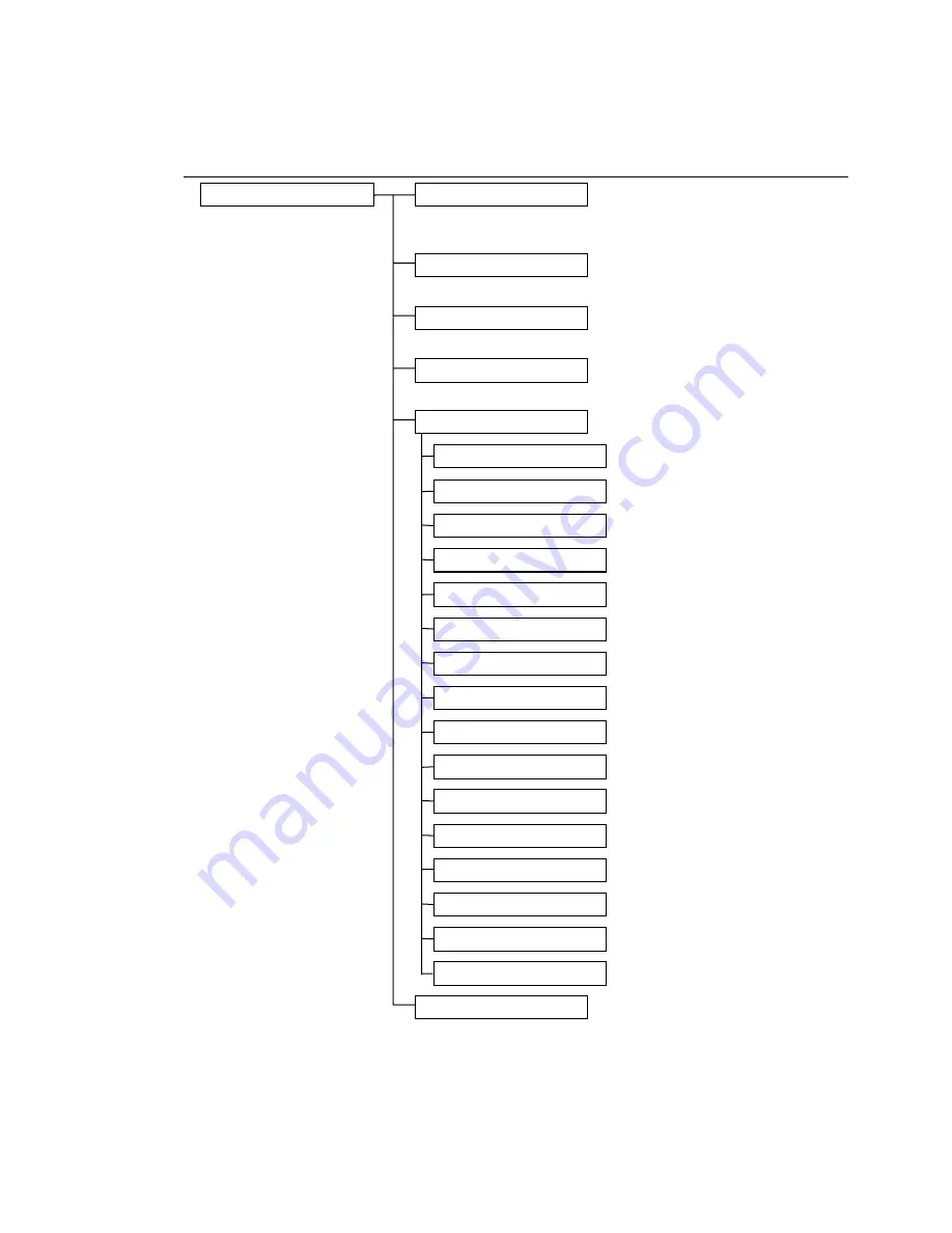
Adjust the voltage to sense toner
empty. Standard toner empty
sensing.
This is chosen by default.
Suitable or MICR cartridge.
(Voltage for the tonere empty
sense is -0.3V)
Set the voltage for the tonere
empty sense at -0.1V

Set the voltage for the tonere
empty sense at -0.2V

Set the voltage for the tonere
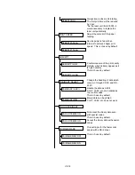
empty sense at -0.7V
-0.6V

-0.5V

-0.4V

-0.3V

-0.2V

-0.1V

0V

+0.1V

+0.2V

+0.3V

+0.4V

+0.5V

+0.6V

+0.7V

+0.7V (Same as SPECIAL CART.
15)
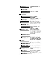
Automatic setting

EP/ED CART

REFILL CART. MODE

MICR CART

REFILL CART1

REFILL CART2

SPECIAL

SPECIAL CART. 1

SPECIAL CART. 2

SPECIAL CART. 3

SPECIAL CART. 4

SPECIAL CART. 5

SPECIAL CART. 6

SPECIAL CART. 7

SPECIAL CART. 8

SPECIAL CART. 9

SPECIAL CART. 10

SPECIAL CART. 11

SPECIAL CART. 12

SPECIAL CART. 13

SPECIAL CART. 14

SPECIAL CART. 15

SPECIAL CART. 16

AUTO ADJUST

Содержание HL-2060

Страница 1: ...MECHANICS ELECTRONICS SERVICE MANUAL LASER PRINTER ...

Страница 2: ... of Brother Industries Ltd Centronics is a registered trademark of Genicom Corporation PostScrip is a registered trademark of Adobe Systems Incorporated IBM Proprinter XL is a registered trademark of International Business Machines Corporation EPSON FX 850 is a registered trademark of Seiko Epson Corporation HP GL and HP Laser Jet 5 are registered trademarks of Hewlett Packard Company ...

Страница 3: ...uitable location disassembling and reassembling procedure of mechanical system CHAPTER V MAINTENANCE AND SERVICING Parts replacement schedule list of tools lubricants and cleaners CHAPTER VI TROUBLESHOOTING Reference values and adjustment troubleshooting for image defects troubleshooting for malfunctions etc APPENDICES Engin Block Daiagram PCB Circuitry Diagrams etc Information in this manual is s...

Страница 4: ... Unsealed EP ED HC Cartridges I 10 CHAPTER II THEORY OF OPERATION II 1 1 BASIC OPERATIONS II 1 1 1 Mechanical Configuration II 1 1 2 Main Drive II 2 1 3 Basic Sequence of Operations II 3 2 LASER SCANNER SYSTEM II 4 3 IMAGE FORMATION SYSTEM II 5 3 1 Outline II 5 3 2 Printing Process II 5 3 2 1 Electrostatic latent image formation stage II 6 3 2 2 Developing stage II 8 3 2 3 Transfer stage II 9 3 2 ...

Страница 5: ...ECHANICAL SYSTEM IV 1 PRINTER DISASSEMBLING PROCEDURE IV 2 PRINTER BODY IV 3 1 1 Configuration IV 3 1 2 Control Panel Unit IV 3 1 3 Toner Cartridge Lid IV 3 1 4 Side Cover L IV 4 1 5 Font Cover Assy IV 5 1 6 Upper Cover Assy Rear Cover Assy IV 5 1 6 1 Upper cover assy rear cover assy IV 5 1 6 2 Changeover guide jam remove cover IV 7 1 7 Side Cover R IV 7 1 8 DC Fan Motor IV 8 1 9 Main PCB IV 9 1 1...

Страница 6: ...y PCB Assy IV 29 1 33 Low Voltage Power Supply PCB Assy IV 30 1 34 Toner Cartridge EP ED HC Cartridge IV 31 1 35 Paper Tray IV 32 CHAPTER V MAINTENANCE AND SERVICING V 1 1 PERIODICAL REPLACEMENT PARTS V 1 2 CONSUMABLE PARTS STANDARD ENDURANCE TABLE V 1 3 LIST OF STANDARD TOOLS V 2 4 LIST OF LUBRICANTS AND CLEANERS V 3 CHAPTER VI TROUBLESHOOTING VI 1 1 INTRODUCTION VI 1 1 1 Initial Check VI 1 1 2 B...

Страница 7: ...down CONT SEL keys VII 17 APPENDIX A 1 Engine Block Diagram A 1 2 Paper Feed Size SW PCB Circuitry Diagram 1 1 A 2 3 Main PCB Circuitry Diagram 1 7 A 3 4 Main PCB Circuitry Diagram 2 7 A 4 5 Main PCB Circuitry Diagram 3 7 A 5 6 Main PCB Circuitry Diagram 4 7 A 6 7 Main PCB Circuitry Diagram 5 7 A 7 8 Main PCB Circuitry Diagram 6 7 A 8 9 Main PCB Circuitry Diagram 7 7 A 9 10 Control Panel PCB Circu...

Страница 8: ... Radiological Health CDRH E Paper can be fed in two ways by the multi purpose paper feed tray and paper cassette F Maintenance is easy with print component units which are directly detachable and they require no adjustment after reassembly 2 SPECIFICATIONS 1 Type Desktop page printer 2 Printing method Electrophotography single component dry toner 3 Printing speed Cassette feed 20 ppm 600 x 600 dpi...

Страница 9: ...etter size paper with the print density set at level 8 with 5 coverage recommended 60 g m 2 105 g m 2 Multi purpose Tray Plain paper of 95 x 148 mm 216 x 356 mm recommended 60g m 2 200 g m 2 overhead projector OHP film postcards label stock and envelopes specified sizes 10 Cassette Tray 1 Paper cassette A4 Letter Legal Universal Option A4 Letter Legal Executive ISO B5 A5 ISO B6 A6 and approx 20 en...

Страница 10: ...1 0 Legal 215 9 355 6 207 4 347 1 4 23 1 0 B5 ISO 176 0 250 0 167 5 241 5 4 23 1 0 Executive 184 2 266 7 175 7 258 2 4 23 1 0 A5 148 0 210 0 139 5 201 5 4 23 1 0 B6 ISO 125 0 176 0 116 5 167 5 4 23 1 0 A6 105 0 148 0 96 5 139 5 4 23 1 0 Table 1 2 Envelope SIZE A mm B mm C mm D mm E mm COM 10 104 8 241 3 96 3 232 8 4 23 1 0 MONARCH 98 4 190 5 89 9 182 0 4 23 1 0 DL 110 1 221 0 101 6 212 5 4 23 1 0 ...

Страница 11: ...d Landscape Letter Gothic 16 66 Medium Italic Bold Bold Italic OCR A OCR B Intellifont Compatible Fonts Albertville Extrabold Antique Oakland Oblique Bold Brougham Oblique Bold Bold Oblique Cleveland Condensed Connecticut Guatemala Antique Italic Bold Bold Italic Letter Gothic Oblique Bold Maryland Oklahoma Oblique Bold Bold Oblique PC Brussels Light Light Italic Demi Demi Italic PC Tennessee Roma...

Страница 12: ...1 3 kPa 0 2 500 m above sea level Non operating Temperature 0 35 C environment Relative humidity 10 80 RH No condensation allowed Storage conditions Printer Temperature Normal total storage time x 9 10 0 35 C Severe total storage time x 1 10 High Low 35 C 60 C 20 C 0 C Temperature change within 3 minutes High Low 60 C 15 C 20 C 25 C Atlanta Book Book Oblique Demi Demi Oblique Brussels Light Light ...

Страница 13: ...5 95 RH 10 35 RH Air pressure 71 0 101 3 kPa Maximum total storage time 2 5 years including used time 3 SAFETY INFORMATION 3 1 Laser Safety 110 120V Model only This printer is certified as a Class 1 laser product under the US Department of Health and Human Services DHHS Radiation Performance Standard according to the Radiation Control for Health and Safety Act of 1968 This means that the printer d...

Страница 14: ...anger of exposure to laser radiation exist CAUTION INVISIBLE LASER RADIATION WHEN OPEN AND INTERLOCK DEFEATED AVOID DIRECT EXPOSURE TO BEAM CLASS 38 LASER PRODUCT ADVARSEL USYNLIG LASER STRÅLING NÅR KABINETLÅGET STÅR ÅBENT UNGDÅ DIREKTE UDSÆTTELSE FOR STRÅLING KLASSE 38 LASER VARNING OSYNLIG LASERSTRÅLNING NÄR DENNA DEL ÄR ÖPPNAD OCH SPÄRRAR ÄR URKOPPLADE STRÅLEN ÄR FARLIG KLASS 38 LASER APPARAT V...

Страница 15: ...ry port 2 Control panel 9 Centronics interface connector 3 MP tray 10 RS 232C interface connector 4 Tray 1 11 USB port 5 Power switch 12 Duplex unit Lower tray unit connector 6 PCMCIA card slots 13 Rating label 7 Fan outlet port 14 AC inlet Figure 1 4 1 11 3 9 12 14 13 10 2 8 5 4 6 7 ...

Страница 16: ... EP ED HC cartridge 10 High voltage power supply assy 3 Photosensitive drum 11 Paper cassette Tray 1 4 Laser unit 12 Pick up rollers 5 Transfer unit 13 MP tray 6 Face down tray 14 Registration rollers 7 Print delivery path 8 Fixing unit Figure 1 5 1 11 3 9 12 14 13 10 2 8 5 4 6 7 ...

Страница 17: ... contains a photosensitive drum that has an organic photoconductor OPC which deteriorates when exposed to strong light It also contains toner The user therefore should be fully informed about the correct storage and handling of EP ED HC cartridges 1 Storage requirements 1 Avoid places exposed to direct sunlight or near a window Do not leave an EP ED HC cartridge in a car in warm or hot weather eve...

Страница 18: ...transmission of groups of signals 1 BASIC OPERATIONS 1 1 Mechanical Configuration The printer functions can be divided into four blocks the laser system the image formation system the paper pick up feed system and the control system Expansion memory SIMM Font card Optional I O MIO External Device Control panel IMAGE FORMATION SYSTEM Cleaning unit Photosensitive drum Developing unit Laser unit LASE...

Страница 19: ...l SDRIVE output from the main PCB Main motor Main motor drive signal MDRIVE Main PCB Drum gear Photosensitive drum Fixing unit Paper delivery rollers Paper feed motor Paper feed motor drive signal MP tray pick up roller solenoid drive signal MPSOL MP tray pick up roller solenoid MP tray pick up roller Tray1 pick up roller solenoid drive signal PUCL1 Tray1 pick up roller solenoid Tray1 pick up roll...

Страница 20: ... on A4 paper Power on Print WAIT STBY PRINT Ready lamp Fixing heater Main motor 180 C control 210 C STBY control 180 C control Laser unit motor Paper feed motor Pick up roller solenoid Laser diode Registration sensor 0 18 sec 0 12 sec 1 50 sec 1 38 sec 2 54 sec Figure 2 3 ...

Страница 21: ...eam modulated by DATA The modulated laser beam is aligned into a parallel beam by a collimator lens and a cylindrical lens and then brought to the scanning mirror which is rotating at a constant speed The laser beam reflected by the scanning mirror focuses on the photosensitive drum via the focusing lenses arranged in front of the scanning mirror The path of the beam coming through the focusing le...

Страница 22: ...s The major part of the image formation system is contained in the cartridge as shown in Figure 2 5 Figure 2 5 The cartridge used by the printer has a seamless photosensitive drum with the structure shown in Figure 2 6 The outer layer of the drum consists of an organic photoconductor OPC the base is aluminum The printing process can be divided into five major stages Figure 2 6 1 Electrostatic late...

Страница 23: ... 3 Develop ment Figure 2 7 3 2 1 Electrostatic latent image formation stage This stage has two steps which together produce a pattern of electrical charges on the photosensitive drum At the end of the stage negative charges remain in the unexposed dark area Charges are absent from the light areas where the laser beam struck exposed the drum surface Since this image of negative charges on the drum ...

Страница 24: ...ing roller to keep the potential on the drum surface uniform This DC bias is changed with the developing DC bias This charging method has advantages such as lower applied voltage less ozone generation etc compared with the corona charge system Step 2 Scanning exposure _ _ _ Figure 2 10 When the laser beam scans the drum surface it causes the charge to be neutralized in the areas struck by the beam...

Страница 25: ...nd acquires a negative charge by friction due to the rotation of the cylinder The areas on the drum that were exposed to the laser beam have a higher potential are less negative than the negatively charged toner particles on the developing cylinder When these areas approach the cylinder the potential difference projects the toner particles onto them This is called toner projection and the latent i...

Страница 26: ...to jamming etc the toner may adhere to the transfer charging roller The printer removes the toner from the transfer charging roller by switching the transfer voltage between positive and negative in sequence During wait initial rotation and last rotation the printer sets the primary DC voltage to zero and sets the charge on the drum to zero In this case the transfer voltage is made negative to rem...

Страница 27: ...er becoming higher than that of the lower roller resulting in the toner being drawn to the lower roller and adhering to the lower roller surface 3 2 5 Drum cleaning stage In the transfer stage not all the toner is transferred to the paper Some remains on the photosensitive drum This residual toner is cleaned off in the drum cleaning stage so that the next print image will be clear Step 7 Drum clea...

Страница 28: ... by the transfer roller unit Then the residual toner is removed from the drum surface with the cleaner blade The cartridge also has a toner sensor When the output from this sensor falls below a certain level it warns that the EP ED HC cartridge will be out of toner with an alarm Primary charge AC drive HV1AC Primary charge DC drive HV1DC Developing bias AC drive DBAC Developing bias DC drive DBDC ...

Страница 29: ...by the paper ejection sensor if printed paper has not reached or not cleared the paper ejection sensor in a specified time the printer judges that a paper jam has occurred In this case a paper jam is noticed to the external devise by a status signal Main PCB Paper ejection sensor Fixing rollers Transfer roller Main motor Photosensitive drum Registration sensor Tray1 Pick up roller solenoid Paper f...

Страница 30: ...ontroller circuit the paper feed motor starts rotation About 0 2 seconds later the printer actuates the tray1 pick up roller solenoid and the pick up roller makes one rotation This feeds paper to the photosensitive drum Timing chart for the pick up one sheet 0 12 sec 1 74 sec 1 38 sec 2 54 sec Main motor Paper feed motor Registration sensor Paper empty sensor Pick up roller solenoid Paper ejection...

Страница 31: ...te feed Tray1 paper empty sensor MP tray feed MP tray paper empty sensor 2 The pick up roller solenoids are different Cassette feed Tray1 pick up roller solenoid MP tray feed MP tray pick up roller solenoid 0 12 sec 0 12 sec Main motor Paper feed motor Registration sensor Paper empty sensor Pick up roller solenoid Paper ejection sensor STBY PRINT STBY PRNT or PRFD 0 65 sec Figure 2 20 ...

Страница 32: ...1 Paper exists at the paper ejection sensor or the registration sensor when power is switched on JAM REAR or JAM INSIDE 2 Paper has not reached the registration sensor within a specified time JAM TRAYS 3 Printed paper has not passed through the registration sensor within a specified time JAM INSIDE 1 4 Printed paper has not reached the paper ejection sensor within a specified time JAM INSIDE 2 5 P...

Страница 33: ...ensor Paper feed motor Jam check Figure 2 23 Jam rear STBY PRINT Jam Normal 5 74 sec 5 74 sec Main motor Paper ejection sensor Paper feed motor Jam check Figure 2 24 If the stuck full sensor detects a status that the paper is inside the printer for 20 seconds it sends out the full signal ...

Страница 34: ...ne controller circuit 2 Displays the current printer status in LED and LCD and enables settings from the control panel The operation sequence of the printer controlled by a microprocessor in the Engine Controller Circuit The Engine Controller Circuit outputs signals to drive the various loads on the laser diode laser unit motor main motor etc according to the print commands and image data from the...

Страница 35: ...S 232C interface block Centronics parallel interface Data transmission and reception are controlled by the MB87F1611 19 RS 232C Data transmission and reception are controlled by the MB87F1611 19 The ADM202JRN 35 serves as driver receiver 5 SIMM block SIMM Single Inline Memory Module allows memory extension up to 72MB 2 SIMM sockets are available SIMM should be of 72 pin type and its access time sh...

Страница 36: ...EPROM µPD27C8000DZ 120 NEC or equivalent for expansion ROM access time should be less than 120nsec 7 DRAM block DRAMs are used for receiving buffer or working area of the CPU The DRAM block contains four 16Mbit DRAMs thus having 8MB memory capacity in total The refreshing method is CBR Cas Before Ras DRAM access time should be less than 80nsec ...

Страница 37: ...ected it will become one memory space and ROM 0 supports upto 16MB CSROM 3 is a rest of the memory space with 256MB 5E00_0000 5E20_0000 5E40_0000 5E60_0000 5E80_0000 5EA0_0000 5EC0_0000 5EE0_0000 5F00_0000 5F20_0000 5F40_0000 5F60_0000 5F80_0000 5FA0_0000 5FC0_0000 5FFF_FFFF USB HRC GS setting Memory wait setting BD LSB setting Write to LSB DRAM transfer SDRAM mode setting Soft support function FC...

Страница 38: ...nnector SIMM Block MASK ROM Flat package USB I F RS232C I F ASIC MB87F1611 CPU VIDEO Centronics I F Option ROM Socket DRAM Block Control Panel Connector ASIC MPD65632GC CPU ENGINE PCMCIA Card Connector Figure 3 4 Main PCB ...

Страница 39: ... in the Circuit refer to the next page A Engine Control CPU B Low Voltage Power Supply Connector C Fuser Unit Control C 1 Heater Drive Circuit C 2 Heater Temperature Input Signal C 3 Paper Eject Input Signal D Paper Feeder PCB Control Signals and Connector E Option Interface Circuit and Connector F High Voltage Power Supply Control Circuit and Connector G Laser Unit Control G 1 Laser Unit Motor Co...

Страница 40: ...noid Drive Circuit and Connector D Multi Purpose Tray Pick up Solenoid Drive Circuit and Connector E Sensors E 1 Tray1 Paper Empty Sensor E 2 Multi Purpose Tray Paper Empty Sensor E 3 Regist Sensor E 4 Pre Regist Sensor E 5 Paper Detect Sensor in Duplex Unit F Tray1 Paper Size Detect Switches Refer to the next page ...

Страница 41: ...III 8 A B F C D E 1 E 2 E 3 E 4 E 5 F Figure 3 7 Paper Feed Size SW PCB Circuit ...

Страница 42: ...NLINE LED5 ONLINE LED2 DATA SW1 FORMFEED SW4 SEL SW2 UP SW5 FONT SW3 DOWN SW6 SET LED1 READY LED3 ALARM SW8 CONTINUE SW7 MODE Figure 3 8 Display Circuit 3 2 Operation Indicators on the control panel LED lamps and LCD are controlled by the video controller circuit All the switch signals are input to the video controller circuit Signals Descriptions LED1 LED4 On off control for the respective LED la...

Страница 43: ...m the engine controller 24V output is reserved in the DC block for the cooling fan for the low voltage power supply assy 4 2 Protection Functions Each of the power supply circuits 5V and 24V has a protection function to prevent the circuit from accident by automatically cutting off the power supply in the case of a over voltage or over current of the load When the cooling fan stops to rotating an ...

Страница 44: ...L N L N Power Switch SW1 Noise Filter Rectfier Inlet Transformer Rectfier Chopper Over Voltage Detector Feedback Control 1 4 2 3 6 7 5 8 HEAT 24V 5V 5V 0V 0V 24VRET FANLOCK P101 To Heater Circuit F1 F2 P1 Figure 3 9 Low Voltage Power Supply PCB Block Diagram ...

Страница 45: ...veloper bias DC changes according to values of the input signal DNSTY which is for print density adjustment like the primary high voltage DC 3 Transfer charging Transfer bias is controlled by the input signals HVT1 4 and HVTFB When the input signal HVT1 gets the Low level and the input signal HVT4 gets 3 7V negative high voltage is applied to the transfer roller When the input signal HVT2 gets the...

Страница 46: ...t DNSTY Control Circuit ON OFF Circuit Feedback Circuit Pulse Generator Control Unit Feedback Circuit ON OFF Circuit Control Unit DNSTY Control Circuit ON OFF Circuit Feedback Circuit PULSE DEVELOPER BIAS DC DEVELOPER BIAS AC PULSE PRIMARY HIGH VOLTAGE DC PRIMARY HIGH VOLTAGE AC 1 5 2 3 4 HV1AC DNSTY HV1DC DBAC DBDC P2 High Voltage Electrode P4 DBOUT 16 HVHALF Figure 3 10 High Voltage Power Supply...

Страница 47: ... Current Buffer P1 High Voltage Electrode Current Buffer Attenuator Constant Current Control Unit Feedback Circuit ON OFF Circuit Toner Sense Control Unit HVT4 Control Circuit Current Buffer Toner 1 Circuit Toner 2 Circuit P3 Toner Sense Electrode Pulse Generator Constant Voltage Control Unit Figure 3 11 High Voltage Power Supply Block Diagram 2 ...

Страница 48: ...damaged due to the electricity charged in your body 6 When transporting PCBs be sure to wrap them in conductive sheets such as aluminum foil 7 Be sure to reinsert self tapping screws correctly if removed 8 Unless otherwise specified tighten screws to the torque values listed below Tapping screws S tight M3 7kgf cm B tight M3 x 6 5kgf cm M3 x 8 7kgf cm Stepped screws M3 7kgf cm M4 10kgf cm 9 When c...

Страница 49: ... R Paper feed chassis unit Side cover R Regist sensor actuator P feed size SW PCB ASSY Size switch spring Paper path separation plate PS switch wire Remote switch Latch Transfer unit DC gear holder ASSY High voltage power supply unit Low voltage power supply unit PE sensor actuator Tray sensor holder Roller holder Paper pick up roller Paper feed motor ASSY Font cover ASSY Toner cartridge Paper tra...

Страница 50: ...e Control panel unit and remove the 3 screws from the Interlock actuator 4 Pull out the Harness connector Note Carefully remove the Panel cover from the rib Figure 4 2 Toner cartridge lid Upper cover ASSY Control panel unit Side cover L Paper tray Rear cover ASSY Side cover R Font cover ASSY Screw Screw Control panel unit Bottom Lead wire cover Interlock actuator ...

Страница 51: ...t towords the left side 4 Push the left side of the Toner cartridge lid to release the boss 5 Remove the Toner cartridge lid from the Upper cover Figure 4 3 1 4 Side Cover L 1 Release the lock by pinching the lever on the left top surface and remove the cover by pulling it rearward Figure 4 4 Cleaner brush Hook lever Side cover L A Toner cartridge lid Upper cover ASSY Supporter Open the Toner cart...

Страница 52: ...n the top left screw and 2 screws at the top of the Rear cover ASSY 2 Release the hook at the right side of the Upper cover ASSY and lift it upwards to remove Note Pay attention to the Paper sensor actuator when removeing the Upper cover ASSY The hook is released automatically by removing the Upper cover ASSY in the direction of the arrow Figure 4 6 Screw Hook Font cover ASSY Hook Upper cover ASSY...

Страница 53: ...cover ASSY Figure 4 7 4 Disconnect the Paper eject sensor harness from the Paper eject sensor PCB ASSY Figure 4 8 5 Remove the Rear cover ASSY Upper cover ASSY Rear cover ASSY Screw Screw Paper ejetct sensor PCB Paper ejetct sensor harness Rear cover ASSY ...

Страница 54: ... the boss both on sides toward the front 3 Remove the changeover guide from the boss by bending the right hook viewed from the rear of the Rear cover ASSY then remove the changeover guide Figure 4 9 1 7 Side Cover R 1 Remove the screw and remove the Front cover Figure 4 10 C D Jam remove cover Hole Boss Rear cover ASSY Changeover guide Dents A B C E D E B A Screw Front cover Hook Hook ...

Страница 55: ...igure 4 11 1 8 DC Fan Motor 1 Remove the DC fan motor from the DC fan motor holder by loosening the 2 screws 2 Loosen the screws securing the Holder spacer and remove the entire DC fan motor holder Figure 4 12 Rear Front Side cover R Hook at 4 places DC fan holder 2 screws Screws yellow DC fan motor Holder spacer ...

Страница 56: ...IV 9 1 9 Main PCB 1 Loosen the 2 screws and remove the SIMM replace lid Figure 4 13 2 Remove the 7 screws and the MIO box Figure 4 14 MIO box Screws Screw SIMM replace lid ...

Страница 57: ...harness 4P the Porigon harness 5P the LSR flat cable 6P the DC motor harness 5P the HV harness 16P and the LV harness 8P Figure 4 16 PCB holder Screws Main PCB PCB holder View from the top Centronics connector lock wire Paper feed flat cable 21P Porigon harness 5P HV harness 16P DC motor harness 5P LV harness 8P SW panel harness 22P Fuser harness 4P LSR flat cable 6P LSR fan motor harness 2P LV fa...

Страница 58: ... the chassis by loosening the screws 3 Remove the Laser unit from the chassis by loosening the screws Caution Do not disassemble the Laser unit it can be only adjusted at the factory only 8 screws Main PCB ASSY LSR flat cable 6P connector LSR harness 14P Laser unit Screws Screws Beam Polygon control PCB Release the hook to loosen the cable tie Figure 4 18 Figure 4 19 ...

Страница 59: ...ews Figure 4 20 4 Remove the screw for the Laser fan motor and remove it 5 Remove the Laser flat cable form the ferrite core 6 Loosen 4 screws and remove the Laser unit mount plate in the direction of the arrow the Ground leaf spring is also released at the same time Figure 4 21 M holder Ground leaf spring Screws Front Rear Left side Right side Laser unit mount plate Cartridge stopper ASSY LSR har...

Страница 60: ...ssis Unit 1 Pull out the unit by loosening the 8 screws 4 screws for front and 4 screws for bottom Figure 4 23 Note When installing the Paper feed chassis unit screw the left chassis of this Paper feed chassis unit set the paper tray displace the right chassis of this unit up to the paper tray and screw them Screws Screws Paper feed chassis unit A Laser unit mount plate Cartridge stopper ASSY B C ...

Страница 61: ...t cartridge hold roller and remove the cartridge guide L by loosening the screw and releasing the hook then pull out feed flat cable 20P Figure 4 25 4 Remove the Paper feed chassis unit Figure 4 26 Paper feed chassis unit Screw Hook the rear side Cartridge hold roller Cartridge guide L Feed flat cable 20P Paper hold front Screws Screws Paper hold rear ...

Страница 62: ... Figure 4 27 3 Remove the spring from the Separation pad ASSY Figure 4 28 1 14 MP PE Sub Actuator 1 Pull out the actuator upward from the MP tray ASSY pay attention to the hook because it is fragile Figure 4 29 Separation pad ASSY Separation pad spring Paper feed guide upper Paper pick up roller ASSY Paper pick up roller collars Separation pad ASSY Hook MP PE sub actuator ...

Страница 63: ...eed Size SW PCB ASSY Figure 4 30 1 16 Size Switch Spring 1 Pull out the Size switch spring Figure 4 31 1 17 Regist sensor actuator 1 Remove the actuator by shifting it to the left from the chassis hole Regist sensor actuator Regist sensor actuator Size SW PCB Size switch spring Tabs 2 solenoid harness connector 2 screws P feed size SW PCB ASSY Paper feed motor harness connector Figure 4 32 ...

Страница 64: ...g it from the chassis PE sensor actuator tray PE actuator link DU detection actuator 1 Remove the PE actuator link from the PE sensor actuator tray 2 Remove the PE actuator link from the Tray sensor holder 3 Remove the PE sensor actuator tray from the Tray sensor holder 4 Remove the DU detection actuator from the Tray sensor holder Figure 4 34 PE sensor actuator MP PE sensor actuator MP DU detecti...

Страница 65: ...e 4 35 1 21 Paper pick up roller ASSY Bearing 1 Pull out the MP paper pick up gear 35 and the Tray paper pick up gear 35 from the Paper pick up roller shafts Figure 4 36 Bearings MP paper pick up gear 35 Paper pick up roller shafts Tray paper pick up gear 35 Gear 28 Roller holder Screws ...

Страница 66: ... the body assembled Figure 4 37 3 Pull out the Paper pick up roller shafts 4 Remove the Paper pick up roller collars from the Paper pick up rollers ASSY Figure 4 38 Bearing Paper pick up roller ASSY Bearing Paper pick up roller shafts Paper pick up roller collars Paper pick up roller ASSY Collars stopper Paper pick up roller ASSY Paper pick up roller collars Paper pick up roller collars ...

Страница 67: ...each solenoid by loosening their screw Figure 4 39 1 23 Paper Feed Motor ASSY 1 Pull out the Paper feed motor ASSY by loosening its 2 screws Figure 4 40 Screw Paper pick up solenoid Screw Paper pick up solenoid Paper feed motor ASSY Screw Screw ...

Страница 68: ...1 24 MP Tray Cover 1 Remove the MP tray cover from the Paper feed chassis unit by bending its hook on both sides Figure 4 42 Hook Hook MP tray cover Paper feed chassis unit MP extension tray Paper feed roller ASSY 70s Washer Screw Washer Screws Paper feed roller ASSY 60 Bearings Bearing Washer Washer Washer Washer ...

Страница 69: ...mer Figure 4 43 1 25 MP Tray ASSY 1 Remove the MP tray ASSY from the MP tray cover by bending its bosses Figure 4 44 2 Remove the 2 fixing bushes 3 Remove the MP tray ASSY Figure 4 45 MP extension tray MP tray cover Boss Boss MP tray ASSY MP tray cover MP tray ASSY Fixing bushes ...

Страница 70: ...on Plate Paper Path Separation Film 1 Remove them from the Paper feed guide lower by bending them Figure 4 47 1 27 Latch 1 Remove the latch from the Paper feed guide upper by releasing the 2 hooks Figure 4 48 Paper feed guide upper Hook Latch Hook Boss MP tray ASSY Boss MP release plate Paper feed guide lower Paper path separation plate Paper path separation film ...

Страница 71: ...he fixing unit by pulling it to the rear Figure 4 49 4 Take off the Halogen heater by removing 2 screws at the both side remove the Halogen heater Figure 4 50 Note Do not use the electric driver as the Halogen heater is easy to break Do not touch the Halogen heater glass If finger prints are on it clean it with a cloth dampen with iPA alcohol When reassembling make sure The terminal of the heater ...

Страница 72: ...Fixing unit cover Note When removing the Fixing unit cover the Thermistor cleaner ASSY and the spring come off from the Fixing unit cover Insert the Thermistor cleaner ASSY together with the spring into the correct possition first and start reassembling See Figure 4 50b Figure 4 51 Figure 4 52 Screws Fixing unit chassis Fixing unit cover Hooks Screws Thermistor cleaner ASSY Spring ...

Страница 73: ...retaining rings on both sides 2 Remove the HR gear loosen the screw and remove the spring washer remove the left and right HR bearings and the heat roller by sliding it Figure 4 55 Screw Fixing PCB ASSY Connector 2P Paper delivery actuator Fixing unit cover Thermistor Screw Retaining ring Spring washer Retaining ring HR gear Heat roller HR bearing HR bearing ...

Страница 74: ... spacer L R may help to assemble springs 1 29 Transfer Unit 1 Loosen a screw 2 Release the 3 right hooks see Figure 4 57 lift the right part of the unit A and slide it to the right B See Figure 4 56 to take off the left part from the main chassis L Remove the transfer unit from the body by lifting the former Figure 4 57 Pressure roller bearing Pressure roller Fixing unit chassis Pressure roller sp...

Страница 75: ... ASSY 1 Remove the DC motor connector then remove the Paper delivery holder spring 2 Loosen the 4 screws and remove the DC gear unit from the chassis 3 Remove the Paper delivery gear ASSY the gears the Gear 48 spring and the washer 4 Loosen the 3 screws and remove the DC motor ASSY from the gear holder Figure 4 60 Figure 4 59 3 Hooks Transfer roller ASSY Transfer base ASSY PS switch wire Paper del...

Страница 76: ...order to release the chassis caught at 2 places 2 Remove the remote switch from the chassis 1 32 High Voltage Power Supply PCB ASSY 1 Release the 2 hooks at the bottom of the LV duct and slid it towards the left Lift it upwards to remove 2 Remove the LV fan Figure 4 63 Figure 4 62 Figure 4 61 Switch attachment PS switch wire Remote switch Chassis Remote switch LV fan LV duct ...

Страница 77: ...osite side B Figure 4 64 1 33 Low Voltage Power Supply PCB ASSY 1 Be sure to remove the heat insulation cover before removing the low voltage power supply block Figure 4 65 Heat insulation cover Hook Hook Heat insulation cover A B C Resin spacers High voltage power supply PCB ASSY The PCB can be detached without removing this Screws Connector ...

Страница 78: ... the spring washer on the Low voltage power supply PCB 5 Disconnect the LV harness 8P Figure 4 66 1 34 Toner Cartridge EP ED HC Cartridge 1 Open the Toner cartridge lid and pull out the toner cartridge Figure 4 67 EP ED HC cartridge Screw Screw Screw PS switch wire Screw Screw Low voltage power supply PCB ASSY LV harness 8P ...

Страница 79: ...older by pulling it out upward 2 Remove the roller 3 Remove the Separation pad ASSY pull it out by turning it Figure 4 68 Figure 4 69 Roller Roller holder Paper tray A4 size Roller holder fixing pawl Separation pad ASSY and spring Earth spring Paper stopper Paper tray legal letter size ...

Страница 80: ... 115V PART LIFE 100K Fixing unit UH1887001 1 100 000 pages 230V PART LIFE 100K 2 Paper pick up roller ASSY 3 Paper pick up roller ASSY 5 UH2821001 UH1494001 1 1 100 000 pages PART LIFE 100K 3 Separation pad ASSY Separation pad ASSY W UH2393001 UH1500001 1 1 100 000 pages PART LIFE 100K 4 Transfer roller ASSY A UH1834001 1 100 000 pages PART LIFE 100K 5 Laser unit UH1885001 1 200 000 pages PART LIF...

Страница 81: ...driver Phillips screwdriver Phillips screwdriver Flat blade screwdriver Precision flat blade screwdriver M3 M5 M4 M5 M4 M5 11 12 13 14 15 Allen wrench set File fine Allen hex screwdriver Diagonal cutting pliers Needle nose pliers M4 16 17 18 19 20 Pliers Snap ring pliers ext 19 30 mm Crimper Tweezers Ruler 21 22 23 24 25 Mallet plastic head Brush Penlight Bottle plastic Solder 26 27 28 29 30 Desol...

Страница 82: ...leaning of plastic rubber and external parts Purchase locally 2 MEK methyl ethyl ketone CH3CO C2H5 Cleaning for oil and toner stains Purchase locally Highly flammable keep away from flame 3 Lubricating oil silicon grease KS64F For fuser Tool No ZX 43D Equivalent oil may be used 4 Lubricating oil Moly kote EM 30L For drive mechanism Tool No ZX 43N Equivalent oil may be used ...

Страница 83: ...isplay when a cartridge is installed in the printer If the message is displayed replace the cartridge with a new one If blank spots occur on prints take out the EP ED cartridge and slowly rock it to distribute the toner evenly 4 Others Check if The transfer guide and feed guide are clean If not clean them with a damp cloth Condensation When the printer is moved from a cold room into a warm room in...

Страница 84: ...CHANICAL CHECK 2 1 Test Printing If an image problem occurs follow the procedure below to produce a test print 1 Enter the offline mode 2 Press the SHIFT and TEST switches simultaneously so the printer enters the test print mode 3 Press the or switch to appear the message TEST PRINT then press the SET switch The message 05 TEST PRINT will appear on the status display of the control panel and the D...

Страница 85: ... All black I 6 Dirt on back of paper I 7 Black vertical streaks I 8 Black and blurred vertical stripes I 10 Black and blurred horizontal stripes I 11 Dropout I 12 White vertical streaks I 13 Faulty registration I 14 Poor fixing I 5 Polka dots I 9 Black and thin horizontal streaks Figure 6 2 ...

Страница 86: ...ean the transfer roller Use dry lint free paper producing little paper dust to clean the transfer roller Never use solvents and if dirt subsists replace the transfer roller assy Transfer input signal error 7 Do the pins 7 and 8 of the connector P6 on the main PCB have the following value respectively when a sheet of paper is fed from the MP tray P6 7 pin HVT2 Change in voltage from 15V approx to 0...

Страница 87: ...anged on the control panel Yes Adjust the proper setting on the control panel EP ED HC cartridge 2 Does printed image improve when the EP ED HC cartridge is replaced Yes Replace the EP ED HC cartridge Dirt on the grounding terminal 3 Does printed image improve when continuity is improved by cleaning the EP ED HC cartridge grounding terminal and the printer unit grounding terminal Yes Clean the con...

Страница 88: ...ness Failure in development high voltage circuit No Replace the high voltage power supply PCB assy I 4 All black Possible cause Step Check Result Remedy Beam detection error 1 Is the printer hung up with the PRINT message remaining on the display even after a printing when only a copy is printed Yes Replace the laser unit or the harness EP ED HC cartridge 2 Does printed image improve when the EP E...

Страница 89: ... EP ED HC cartridge and remove the paper in the printer Is there already dirt on the back of the sheet thus removed No Go to Step 6 Dirt on the transfer roller 3 Is there any dirt on the transfer roller Yes Clean the transfer roller and if the dirt remains replace the transfer roller assy Transfer input signal error 4 Does the voltage at the 6 pin HVT1 of the connector P6 on the main PCB change fr...

Страница 90: ...Are there vertical stripes on the drum No Replace the fixing unit I 9 Black and thin horizontal streaks Possible cause Step Check Result Remedy Beam detection error 1 Replace the laser unit or the harness and if the problem is not resolved replace the main PCB assy I 10 Black and blurred horizontal stripes Possible cause Step Check Result Remedy Drum or charging roller failure 1 Do stripes appear ...

Страница 91: ...7 changes from 0V to 15V No Replace the main PCB assy or the harness Dirt on power supply terminal 6 Clean the transfer roller right end bearing the check continuity between the transfer roller power supply spring and the terminal of the No Clean the contact to assure the continuity Failure in the transfer high voltage circuit high voltage transfer unit Is there continuity Yes Replace the high vol...

Страница 92: ...ssemble the actuator and if the problem is not resolved replace the actuator Regist sensor failure 8 Is the voltage at the pin 5 of the connector P3 of the main PCB 5V when no paper passes and 0V when paper passes No Replace the paper feed size sw PCB assy or the harness and if the problem remains replace the main PCB assy Paper feed roller failure Yes Replace the paper feed roller assy I 14 Poor ...

Страница 93: ... through switch operations Check following signals using the digital memory scope with the trigger function for this check No Replace the main PCB assy the switch flat cable or the control panel unit M 3 Malfunction of control panel LED lamps Possible cause Step Check Result Remedy LED lamps 1 Dose the voltage of the following signals stay 0V while the 04 SELF TEST is displayed Yes Replace the con...

Страница 94: ...en if a paper loaded cassette is mounted or even if a paper is set on MP tray XX is MP T1 T2 Possible cause Step Check Result Remedy Mis operation 1 Is the paper feed mode set correctly No Set paper feed mode correctly Actuator 2 Does the actuator for the paper empty sensor operate smoothly No Reassemble or replace the actuator Paper empty sensor Feed flat cable 3 Does the voltage of P5 3 or P5 14...

Страница 95: ...High voltage power supply PCB 3 Is the voltage of P2 13 in high voltage power supply PCB connector higher than that of P2 11 when the EP ED HC cartridge which is full with toner is installed Yes Replace the high voltage power supply PCB assy HV harness 4 Is the voltage of P6 13 in the main PCB connector higher than that of P6 11 Yes Replace the HV harness Main PCB No Replace the main PCB assy M 9 ...

Страница 96: ...d mode set correctly No Set paper feed mode correctly Main PCB 2 Does the voltage of P3 20 or 19 in the main PCB connector rise from 0V to 5V and is a pulses having about 11ms period generated at P3 6 7 8 9 pin No Replace the main PCB assy Feed flat cable 3 Does the voltage of P5 20 or 19 in the paper feeder PCB Connector rise from 0V to 5V and is the pulses having about 11ms period generated at P...

Страница 97: ...0V 6 3V 10 4 5 9 DBDC 0V 9 8V 5 DNSTY 1 0 4 0V Default 1 9V 10 11 12 13 14 6 15 7 16 8 17 9 18 19 20 HVT1 0V 23 0V 10 12 13 14 15 7 8 17 9 18 19 20 HVT2 0V 17 6V 10 13 14 15 8 9 18 19 20 HVT3 0V 10 0V 10 14 15 9 HVT4 0 2 5 0V 10 15 HVTFB 0 2 5 0V 11 12 13 14 15 16 17 18 19 20 TONER1 0 0 3 5V 12 13 14 15 0V 0V 13 14 15 18 19 20 TONER2 2 0 4 5V 14 15 24VRET 0V 15 24V 24V 16 17 18 19 20 HVHALFN 0 0 1...

Страница 98: ...in PCB 5 Make sure if The EP ED HC cartridge is installed in the printer correctly The upper cover of the printer is closed A paper loaded cassette is mounted No Replace the main PCB assy Note When the printer has detected a fixing unit malfunction do not power on for about 15 minutes Even if the power is on the printer will shut off the power supply to the fixing heat roller to prevent the fixing...

Страница 99: ...displayed Possible cause Step Check Result Remedy Main PCB 1 Does this problem frequently occur No Since this is a temporary problem remove the paper used when the error occurred and continue to print Yes Replace the main PCB assy ...

Страница 100: ...owing three blocks 1 The paper pick up block The LCD display JAM TRAYS 2 The separation and feed block The LCD display JAM INSIDE 3 The fixing and paper delivery block The LCD display JAM REAR Therefore remedies for paper jam problems are described Respectively for these three blocks Figure 6 3 3 2 1 ...

Страница 101: ...Is the separation pad deformed or worn or is it detached Yes Replace the pad assy For solenoid activation no feeder motor operation and no regist sensor activation refer to the item NO PAPER PICK UP FROM THE CASSETTE in the column MALFUNCTIONS J 1b Paper pick up block Oblique feed jam Possible cause Step Check Result Remedy Adjustment lever spring pressure switching lever 1 Is the position of the ...

Страница 102: ...xing unit entrance guide 1 Is the entrance guide dirty Yes Clean the entrance guide Fixing unit Separation guide 2 Is the separation guide worn or deformed Yes Replace the fixing unit Paper delivery actuator 3 Is the paper sensor arm movement smooth Yes Replace the fixing unit Changeover guide 4 Is the changeover guide movement smooth No Replace the changeover guide Delivery rollers Is the deliver...

Страница 103: ... guide broken Yes Replace the paper front guide Separation pad No Replace the separation pad F 2 Wrinkles Possible cause Step Check Result Remedy Print paper 1 Is a recommended type of paper being used No Instruct the user to use recommended type of paper 2 Is the wrinkle problem solved if fresh paper is used Yes Instruct the user in correct print paper storage procedure to be free from moisture P...

Страница 104: ...the CONTINUE switch to check RAM size RAM SIZE 8MB 8M standard RAM SIZE XXMB XX Expanded SIMM 8MB RAM SIZE ERROR In case of error 6 Press the CONTINUE switch to check the fan FAN HIGH SPEED Make sure that the fan rotates at the high speed Press the CONTINUE switch FAN LOW SPEED Make sure that the fan rotates at the low speed 7 Press the CONTINUE switch to check the 1st stage cassette TRAY 1 A4 App...

Страница 105: ...ecks reading writing on Card 1 ID È CARD1 R W OK The flash card works correctly È CARD2 R W START Checks reading writing on Card 2 ID È CARD2 R W OK The flash card works correctly È MIO CHECK START The flash card works correctly È RAM SIZE 8M È Now initializing È LJ WAIT 001P T1 È LJ READY 001P T1 13 Turn off the power Note The checks on and after 11 are carried out automatically and if an error i...

Страница 106: ...alled CARD1 WP SWITCH The Write Protect switch of the flash memory card 1 is on CARD2 WP SWITCH The Write Protect switch of the flash memory card 2 is on 45 MIO ERROR The MIO has a problem NO MIO BOARD No MIO board is installed Now initializing If this message remains displayed the MIO has a problem ...

Страница 107: ...DRESS menu using the scroll buttons iv Whenever the Set button is pressed the LCD will display the DRAM error address on the Main PCB Slot 1 and Slot 2 in turn 6 If a SIMM DRAM has an error replace the SIMM corresponding to the above memory map information If the DRAM on the Main PCB has an error replace referring to the table below Table 6 1 Video Controller DRAM Address Corresponding Table Lower...

Страница 108: ...ard was removed while the printer is on line The duplex unit is not installed with the printer when the duplex printing mode is selected The duplex paper guide tray is not installed in T1 when the duplex printing mode is selected The cover of the duplex unit is open Load a stack of paper into the cassette See M 7 Close the cover See M 6 Remove the jammed paper from the indicated area See M 10 Inst...

Страница 109: ...IMM memory Press the CONTINUE switch to resume printing Data lost in overflow cannot be printed Press the CONTINUE switch to resume printing If the same error should occur after you press the CONTINUE switch turn off the printer Wait a few seconds then turn it on again Reduce the input buffer size Turn off KEEP PCL Add SIMM memory with power off Download font and the font saved in the HDD card mig...

Страница 110: ...alled Notice for replacing the periodical replacement parts Delete unnecessary macros or fonts or use a new card Set the write protect switch of the card to OFF if it has been set to ON Use a new card If the same error occurs consult your dealer or service personal Install the MIO card correctly Check the interface cable connection between the printer and the fitted option Use a new card If the sa...

Страница 111: ...acement parts The output paper tray or the output paper tray of MX 2000 is full of output paper Paper jam at MX 2000 FAX data is sent to a printer with no FAX modem card Replace the following parts of and reset the parts life counter See Page V 1 Laser unit Remove the output paper Clear the paper jam Install a FAX modem card correctly ...

Страница 112: ...X Turn off the printer Wait 15 minutes then turn it on again See M 14 Turn off the printer Wait a few seconds then turn it on again See M 15 Turn off the printer Wait a few seconds then turn it on again See M 16 Turn off the printer Wait a few seconds then turn it on again Turn off the printer Wait a few seconds then turn it on again See M 11 Turn off the printer Wait a few seconds then turn it on...

Страница 113: ...printer Wait a few seconds then turn it on again If still remains replace the main PCB Turn off the printer Wait a few seconds then turn it on again If still remains replace the main PCB Turn off the printer Wait a few seconds then turn it on again If still remains replace the main PCB Turn off the printer Wait a few seconds then turn it on again If still remains replace the main PCB Turn off the ...

Страница 114: ... operation Key s Display Discription Printer test mode for factory use Printer options flash card font cart MIO test mode for factory use Check DRAM Clear NV RAM No display reads Adjust the sensing point of the toner empty Not read toner empty Read toner empty with beep sound Read toner empty with no beep sound Set a printer to work as a standard machine Set a printer to work as a demo machine No ...

Страница 115: ...ite the data which is stored on a PCMCIA card onto flash memory modules on the main ROM socket Write the data recieved through the parallel I F onto flash memory modules on the option ROM socket Write the data which is stored on a PCMCIA card onto flash memory modules on the option ROM socket Write the data recieved through the parallel I F onto patch flash memory modules Write the data which is s...

Страница 116: ...play reads If there is any writing error during writing data onto the patch flash modules the printer becomes unable to initialize itself at power on In this case pressing SEL and MODE keys at power on makes the printer run with the original masked progaram ROM MAIN OPTN ROM W exit MENU MODE SEL ...

Страница 117: ...s and 3 spaces pattern sheet All black sheet White blank sheet 10mm grid pattern sheet for offset print check Continuously print the test pattern sheet Test print sheet 10mm grid pattern sheet Zip 2 dots and 3 spaces pattern sheet All black sheet White blank sheet LINE TEST ENGINE TEST TONER EMPTY TEST LASER TEST MOTOR TEST SENSOR TEST exit ENGINE TEST SINGLE TESTPRINT TEST PRN NORMAL TEST PRN GRI...

Страница 118: ...perature for ragular paper at 20 PPM printing Standard tenperature 5 C from standard temperature 5 C from standard temperature 10 C from standard temperature Adjust the toner fixing temperature for thick paper at 20 PPM printing Standard tenperature 5 C from standard temperature 5 C from standard temperature 10 C from standard temperature Adjust the toner fixing temperature for ragular paper at 10...

Страница 119: ...itch between the standard output tray and the MX output tray From 0 PPM upto 3 5 PPM by 0 5 PPM Adjust the timing to switch between a bin of the MX output tray and another bin of the MX output tray From 0 PPM upto 3 5 PPM by 0 5 PPM Switch the toner density table Countermeasure for the flicker problem The value is 40 by default It can be set in the range of 0 63 Select to use or not to use the pow...

Страница 120: ...et on E1h of IBM chara set Effective setting in EPSON IBM emulation Not make a reprinted chara bold Make a reprinted chara bold Print speed would get slow Create bold italic font from download fonts Not create bold italic font from download fonts Create bold italic font from bitmap fonts Not create bold italic font from bitmap fonts MODE ON OFF MODE ALWAYS ON exit NV RAM CLEAR READOUT SELECT READO...

Страница 121: ...choose 3B PRIO HIGH The priority of selection for 300 dpi bitmap fonts are standard low The priority of selection for 300 dpi bitmap fonts are higer than scalable font Settings for the default font and the panel fixed fonts in EPSON IBM emulation Only similar size fonts are selectable as scalable is selected All fonts are selectable CONDENCE SELECT CONDENCE 16 66p CONDENCE 17 14p OEM FONT SELECT O...

Страница 122: ...OBE signal goes up This is chosen by default ACK signal is sent out when BUSY signal goes down ACK signal is sent out before BUSY signal goes down This is chosen by default Not reset a printer upon INPUT PRIME signal This is chosen by default Reset a printer upon INPUT PRIME signal Not check DSR DR signal when a printer send back data to a host throgh RS 232C This is chosen by default FX XL SCALE ...

Страница 123: ... out XOFF at 11K bytes of the free space remaining Send out XOFF at 21K bytes of the free space remaining Send out XOFF at 101K bytes of the free space remaining Selection of a loacal language for display English French German Dutch Spanish Italian Finnish DSR DR ON INPUT PRIME RCV XON XOFF OFF RCV XON XOFF ON XOFF TIMING SEL XOFF TMG NORMAL XOFF TMG 11K XOFF TMG 21K XOFF TMG 101K exit SERIAL RS 2...

Страница 124: ...utomatic HRC control This is chosen by default Turn ON the automatic HRC control Add DEMO PAGE into TEST menu This is chosen by default Remove DEMO PAGE into TEST menu Debug mode for the printer panel Debug mode for print outs SPRAK NORSK LING PORTUGUESE LANG DANISH REPRINT ON OFF REPRINT JOB REPRINT ON REPRINT OFF ROM DATE DISPLAY DRAM CHECK START DRAM ADDRESS AUTO HRC ON OFF AUTO HRC OFF AUTO HR...

Страница 125: ...er is in ready status Not rotate the fun when a printer is in ready status The fan rotates at low speed when a printer is in ready status This is chosen by default The fan rotates at high speed when a printer is in ready status Set the time to turn ON the fan in the range from 0 sec to 3600 sec by 15 sec Set the time to turn OFF the fan in the range from 0 sec to 3600 sec by 15 sec Rotate the fan ...

Страница 126: ...om 0 sec to 3600 sec by 15 sec Set the time between when MP tray sensor senses paper and starting to feed The value can be selected in the range from 0 msec to 2000 msec by 100 msec This is chosen by default Flash card test mode Flash card test mode Set the first print speed Not rotate a laser unit at power on for the less of laser unit noise This is chosen by default Rotate a laser unit at power ...

Страница 127: ...ing of data which comes in through CDCC and RS 232C Handle the data as ASCII Cntl T Cntl C etc are handled as the control codes This is chosen by default Binary data can be printed Cntl T Cntl C etc does not work Not accept the binary data even with special codes This is chosen by default Accept the binary data with special codes This setting is for the faster print speed with a OS 2 driver This i...

Страница 128: ...eceived by the other interfaces is not processed Even if a printer stays in open connection it is able to process the data received by parallel and serial I F This is chosen by default Process 2 pages data at a time Process 4 pages data at a time This is chosen by default Set PJL JOB TIMEOUT 5 min ON OFF PJL JOB TIMEOUT is effective This is chosen by default PJL JOB TIMEOUT does not carry out BOIS...

Страница 129: ...VII 16 Test for memory MEMORY DISPLAY MEMORY DEBUG MEMORY TEST exit MENU ...

Страница 130: ...nere empty sense at 0 2V Set the voltage for the tonere empty sense at 0 7V 0 6V 0 5V 0 4V 0 3V 0 2V 0 1V 0V 0 1V 0 2V 0 3V 0 4V 0 5V 0 6V 0 7V 0 7V Same as SPECIAL CART 15 Automatic setting EP ED CART REFILL CART MODE MICR CART REFILL CART1 REFILL CART2 SPECIAL SPECIAL CART 1 SPECIAL CART 2 SPECIAL CART 3 SPECIAL CART 4 SPECIAL CART 5 SPECIAL CART 6 SPECIAL CART 7 SPECIAL CART 8 SPECIAL CART 9 SP...

Страница 131: ...This is chosen by default This setting effects PS calculation This is chosen by default TRAY COMMAND MODE TRAY COM NORM TRAY COM SPEC PRINT BLANK PAGE PICKUP RETRY 2 PICKUP RETRY SET TowerFeed ON OFF TowerFeed OFF TowerFeed ON FONT SELECT PAPER TRAY SIZE PARALLEL MENU RS 232C MENU REPRINT ON OFF ROM DATE DISPLAY AUTO HRC ON OFF APPLETALK AT PS PS BINARY SELECT PS QUOTE BINARY PS IMAGE MASK PS CEIL...

Страница 132: ...jam error detection This is chosen by default This is chosen by default 1 page is fixed for the copy page number Settings made on the panel are reset job by job This is chosen by default Turn ON USB function This is chosen by default Turn OFF USB function PRO OFF AUTO PRO OFF NORMAL PROTECT OFF MODE HP ESC E RESET HP ESC E F F HP ESC E COMMAND DPX FF SUP NORMAL DPX FF SUP SPEC DPX FF SUP MODE PS30...

Страница 133: ...nter cannot be cleared without a password This is chosen by default Display the number of the life counter for the periodical replacement parts with 100 000 pages life See page V 1 Reset the life counter for the periodical replacement parts with 100 000 pages life A5 FEED PORT A5 FEED LAND A5 FEED SETTING JAM RECOVER ON JAM RECOVER MODE JAM RECOVER OFF NV RAM CLEAR LINE TEST TEST MENU ENGINE TEST ...

Страница 134: ...umber of the life counter for the periodical replacement parts with 200 000 pages life See page V 1 Reset the life counter for the periodical replacement parts with 200 000 pages life PART 200K 0K PART 200K RESET exit MENU ...

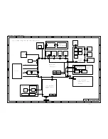
Страница 135: ... A P E R F E E D D R I V E P C B B 5 1 2 0 1 1 2 2 P 1 8 P S F A N 5 P 7 5 3 P 1 2 3 2 P 1 9 2 M A I N M O T O R M A I N F A N S C A N N E R F A N P A N E L P C B B 5 1 2 0 0 5 1 6 X 1 L C D M O D U L E 1 4 1 4 P 2 P 1 2 2 2 2 P 1 T 1 P E S E N S O R E J E C T P C B B 5 1 2 0 0 2 3 3 P 2 1 E J E C T S E N S O R F U S E R P C B B 5 1 2 0 0 8 4 4 2 P 2 P 1 P 1 1 2 P 1 T H E R M O S T A T H E A T E R...

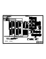
Страница 136: ...Appendix A 2 Paper Feed Size SW PCB Circuitry Diagram 1 1 CODE UK4067000 B512011 012 CIR NAME A 2 ...

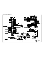
Страница 137: ...Appendix A 3 Main PCB Circuitry Diagram 1 7 CODE UK4058000 B512006 CIR 1 7 NAME A 3 ...

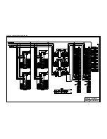
Страница 138: ...Appendix A 4 Main PCB Circuitry Diagram 2 7 CODE UK4058000 B512006 CIR 2 7 NAME A 4 ...

Страница 139: ...Appendix A 5 Main PCB Circuitry Diagram 3 7 CODE UK4058000 B512006 CIR 3 7 NAME A 5 ...

Страница 140: ...Appendix A 6 Main PCB Circuitry Diagram 4 7 CODE UK4058000 B512006 CIR 4 7 NAME A 6 ...

Страница 141: ...Appendix A 7 Main PCB Circuitry Diagram 5 7 CODE UK4058000 B512006 CIR 5 7 NAME A 7 ...

Страница 142: ...Appendix A 8 Main PCB Circuitry Diagram 6 7 CODE UK4058000 B512006 CIR 6 7 NAME A 8 ...

Страница 143: ...Appendix A 9 Main PCB Circuitry Diagram 7 7 CODE UK4058000 B512006 CIR 7 7 NAME A 9 ...

Страница 144: ...Appendix A 10 Control Panel PCB Circuitry Diagram 1 1 CODE UK4077000 B512005 CIR NAME A 10 ...

Страница 145: ...Appendix A 11 Laser LD PCB Circuitry Diagram 1 1 CODE UK3253000 B48K253 CIR NAME A 11 ...

Страница 146: ...nth of Printer A January E May J September B February F June K October C March G July L November D April H August M December ID for production month of other parts than the printer 1 January 5 May 9 September 2 February 6 June X October 3 March 7 July Y November 1 Printer XXXXXXL7S111101 MODEL NO MONTH YEAR FACTORY NO SERIAL NO ...

Страница 147: ...June 98 54T046NE0 HL2060 ...

Отзывы: