II-8
3.2.2 Developing
stage
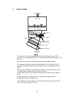
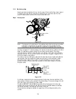
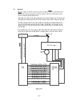
Development places particles of toner onto the areas of the drum that have been cleared
of charge by the laser beam. This makes a visible image. This printer uses the toner
projection development method with a single-component toner.
Step 3 Development
Blade
Stirrer
Developing cylinder
Cylinder
Magnet
DC bias
AC bias
Photo-
sensitive
drum
Figure 2.11
Note: The charges on the light areas on the photosensitive drum are shown as positive
in this figure. Actually they are negative, but they are more positive than the
developing cylinder and explanation is simplified by regarding them as positive.
As shown in Figure 2.11, the developing unit consists of a developing cylinder and rubber
blade. The developing cylinder rotates around a fixed internal magnet. The single-
component toner consists of magnetite and a resin binder, and is held to the cylinder by
magnetic attraction. The toner is an insulator, and acquires a negative charge by friction
due to the rotation of the cylinder.
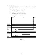
The areas on the drum that were exposed to the laser beam have a higher potential (are
less negative) than the negatively charged toner particles on the developing cylinder.
When these areas approach the cylinder, the potential difference projects the toner
particles onto them. This is called toner projection, and the latent image on the drum
becomes visible.
Developing cylinder
surface potential
Drum surface
potential
(exposed area)
DC bias
Drum surface
potential
(unexposed area)
Time t
+V
0
-V
Voltage (V)
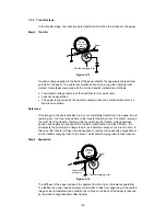
Figure 2.12
An AC bias is applied to the developing cylinder to help project the toner particles to the
drum surface and improve the contrast of the printed image. The center voltage of the AC
bias (1600 Vp-p) varies with the DC bias voltage.
The IMAGE DENSITY ADJUSTMENT signal (sent from the Engine CPU to the high-
voltage power supply) changes the DC bias, and thus the potential difference between
the cylinder and drum. This changes the density of the print.
This printer has a stirring mechanism to supply toner in the cartridge smoothly to the
cylinder.
Содержание HL-2060
Страница 1: ...MECHANICS ELECTRONICS SERVICE MANUAL LASER PRINTER ...
Страница 41: ...III 8 A B F C D E 1 E 2 E 3 E 4 E 5 F Figure 3 7 Paper Feed Size SW PCB Circuit ...
Страница 129: ...VII 16 Test for memory MEMORY DISPLAY MEMORY DEBUG MEMORY TEST exit MENU ...
Страница 136: ...Appendix A 2 Paper Feed Size SW PCB Circuitry Diagram 1 1 CODE UK4067000 B512011 012 CIR NAME A 2 ...
Страница 137: ...Appendix A 3 Main PCB Circuitry Diagram 1 7 CODE UK4058000 B512006 CIR 1 7 NAME A 3 ...
Страница 138: ...Appendix A 4 Main PCB Circuitry Diagram 2 7 CODE UK4058000 B512006 CIR 2 7 NAME A 4 ...
Страница 139: ...Appendix A 5 Main PCB Circuitry Diagram 3 7 CODE UK4058000 B512006 CIR 3 7 NAME A 5 ...
Страница 140: ...Appendix A 6 Main PCB Circuitry Diagram 4 7 CODE UK4058000 B512006 CIR 4 7 NAME A 6 ...
Страница 141: ...Appendix A 7 Main PCB Circuitry Diagram 5 7 CODE UK4058000 B512006 CIR 5 7 NAME A 7 ...
Страница 142: ...Appendix A 8 Main PCB Circuitry Diagram 6 7 CODE UK4058000 B512006 CIR 6 7 NAME A 8 ...
Страница 143: ...Appendix A 9 Main PCB Circuitry Diagram 7 7 CODE UK4058000 B512006 CIR 7 7 NAME A 9 ...
Страница 144: ...Appendix A 10 Control Panel PCB Circuitry Diagram 1 1 CODE UK4077000 B512005 CIR NAME A 10 ...
Страница 145: ...Appendix A 11 Laser LD PCB Circuitry Diagram 1 1 CODE UK3253000 B48K253 CIR NAME A 11 ...
Страница 147: ...June 98 54T046NE0 HL2060 ...

