VII-13
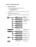
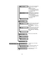
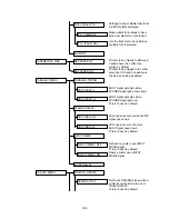
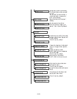
Reverse ON/OFF when a printer is
in the sleep mode.
Not rotate the fan when a printer is
in the sleep mode.
This is chosen by default.
The fan rotates at low speed when
a printer is in the sleep mode.
This is chosen by default.
The fan rotates at high speed
when a printer is in the sleep
mode.
Set the time to turn ON the fan in
the range from 0 sec. to 3600 sec.,
by 15 sec.
Set the time to turn OFF the fan in
the range from 0 sec. to 3600 sec.,
by 15 sec.
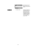
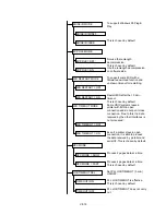
Set the time between when MP
tray sensor senses paper and
starting to feed. The value can be
selected in the range from 0 msec.
to 2000 msec., by 100 msec.
This is chosen by default.
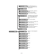
Flash card test mode
Flash card test mode
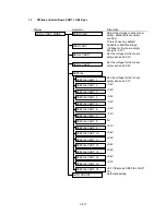
Set the first print speed.
Not rotate a laser unit at power on
for the less of laser unit noise.
This is chosen by default.
Rotate a laser unit at power on.
The first print time will reduced.
SW = ON/OFF
SW = OFF
SPEED = SLOW
SPEED (S)
SPEED = HIGH
ONTIME (S)
FAN ON = 0S
OFFTIME (S)
FAN OFF = 0S
MP FEED TIME
MP FEED=500msec
FLASH CARD CHECK
FLASH CARD CHK2
SPEED=NORMAL
FIRST PRINT
SPEED=MIDDLE
Содержание HL-2060
Страница 1: ...MECHANICS ELECTRONICS SERVICE MANUAL LASER PRINTER ...
Страница 41: ...III 8 A B F C D E 1 E 2 E 3 E 4 E 5 F Figure 3 7 Paper Feed Size SW PCB Circuit ...
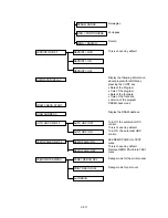
Страница 129: ...VII 16 Test for memory MEMORY DISPLAY MEMORY DEBUG MEMORY TEST exit MENU ...
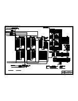
Страница 136: ...Appendix A 2 Paper Feed Size SW PCB Circuitry Diagram 1 1 CODE UK4067000 B512011 012 CIR NAME A 2 ...
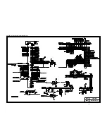
Страница 137: ...Appendix A 3 Main PCB Circuitry Diagram 1 7 CODE UK4058000 B512006 CIR 1 7 NAME A 3 ...
Страница 138: ...Appendix A 4 Main PCB Circuitry Diagram 2 7 CODE UK4058000 B512006 CIR 2 7 NAME A 4 ...
Страница 139: ...Appendix A 5 Main PCB Circuitry Diagram 3 7 CODE UK4058000 B512006 CIR 3 7 NAME A 5 ...
Страница 140: ...Appendix A 6 Main PCB Circuitry Diagram 4 7 CODE UK4058000 B512006 CIR 4 7 NAME A 6 ...
Страница 141: ...Appendix A 7 Main PCB Circuitry Diagram 5 7 CODE UK4058000 B512006 CIR 5 7 NAME A 7 ...
Страница 142: ...Appendix A 8 Main PCB Circuitry Diagram 6 7 CODE UK4058000 B512006 CIR 6 7 NAME A 8 ...
Страница 143: ...Appendix A 9 Main PCB Circuitry Diagram 7 7 CODE UK4058000 B512006 CIR 7 7 NAME A 9 ...
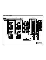
Страница 144: ...Appendix A 10 Control Panel PCB Circuitry Diagram 1 1 CODE UK4077000 B512005 CIR NAME A 10 ...
Страница 145: ...Appendix A 11 Laser LD PCB Circuitry Diagram 1 1 CODE UK3253000 B48K253 CIR NAME A 11 ...
Страница 147: ...June 98 54T046NE0 HL2060 ...

