II-11
3.3 Operation
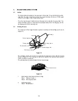
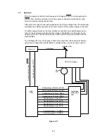
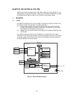
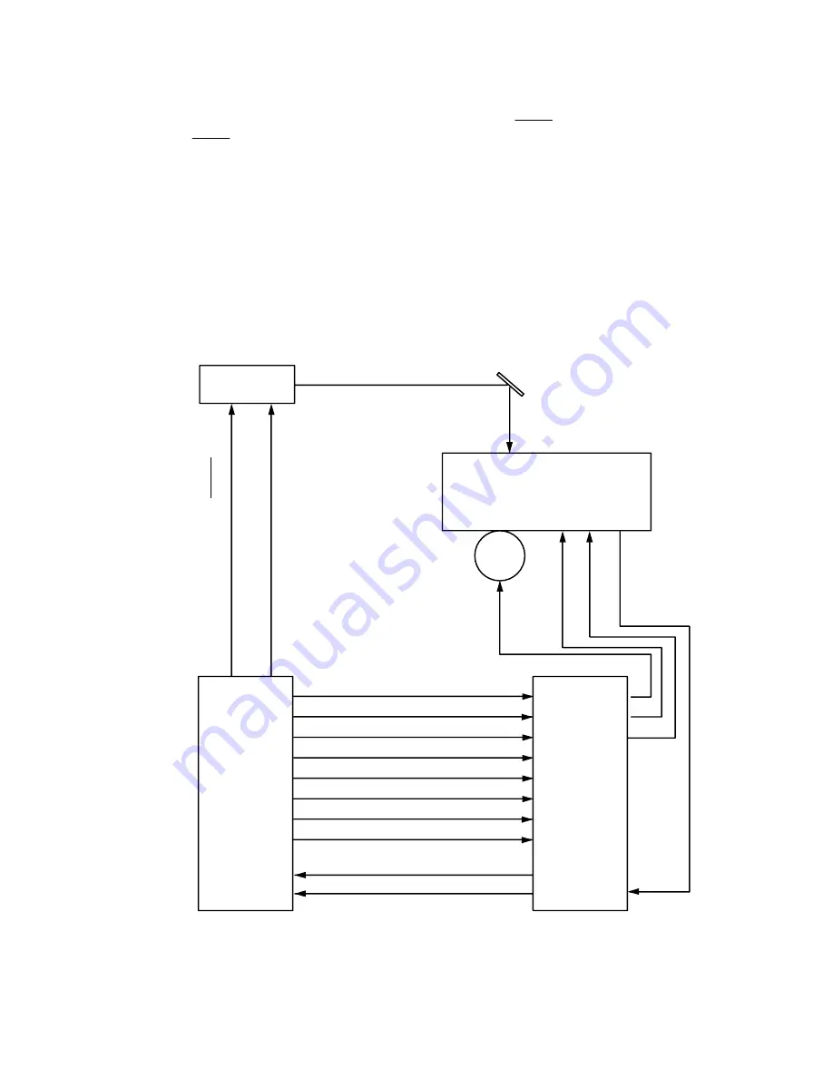
When the engine controller circuit receives a print signal (PRINT) or a pre-feed signal
(PRFD) from the video controller circuit, the engine controller circuit drives the main
motor to rotate the photosensitive drum.
After the drum surface is charged negatively by the primary charge roller, the laser beam
modulated by a DATA signal scans the drum surface to from a latent image on the drum.
The latent image formed on the drum surface is converted into a visible image by the
toner on the developing cylinder and then image is transferred onto the paper by the
transfer roller unit. Then the residual toner is removed from the drum surface with the
cleaner blade.
The cartridge also has a toner sensor. When the output from this sensor falls below a
certain level, it warns that the EP-ED HC cartridge will be out of toner with an alarm.
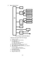
Primary charge (AC) drive (HV1AC)
Primary charge (DC) drive (HV1DC)
Developing bias (AC) drive (DBAC)
Developing bias (DC) drive (DBDC)
Transfer charger 1 drive (HVT1)
Transfer charger 2 drive (HVT2)
Transfer charger 3 drive (HVT3)
Transfer charger 4 drive (HVT4)
Toner sensor signal 1 (TONER 1)
Toner sensor signal 2 (TONER 2)
Main
PCB
Laser unit
EP-ED HC cartridge
Transfer
roller
High-voltage
power supply
PCB
Laser beam
Reflection mirror
Scanner motor drive signal (SDRIVE)
Laser diode drive signal (DATA)
Figure 2.17
Содержание HL-2060
Страница 1: ...MECHANICS ELECTRONICS SERVICE MANUAL LASER PRINTER ...
Страница 41: ...III 8 A B F C D E 1 E 2 E 3 E 4 E 5 F Figure 3 7 Paper Feed Size SW PCB Circuit ...
Страница 129: ...VII 16 Test for memory MEMORY DISPLAY MEMORY DEBUG MEMORY TEST exit MENU ...
Страница 136: ...Appendix A 2 Paper Feed Size SW PCB Circuitry Diagram 1 1 CODE UK4067000 B512011 012 CIR NAME A 2 ...
Страница 137: ...Appendix A 3 Main PCB Circuitry Diagram 1 7 CODE UK4058000 B512006 CIR 1 7 NAME A 3 ...
Страница 138: ...Appendix A 4 Main PCB Circuitry Diagram 2 7 CODE UK4058000 B512006 CIR 2 7 NAME A 4 ...
Страница 139: ...Appendix A 5 Main PCB Circuitry Diagram 3 7 CODE UK4058000 B512006 CIR 3 7 NAME A 5 ...
Страница 140: ...Appendix A 6 Main PCB Circuitry Diagram 4 7 CODE UK4058000 B512006 CIR 4 7 NAME A 6 ...
Страница 141: ...Appendix A 7 Main PCB Circuitry Diagram 5 7 CODE UK4058000 B512006 CIR 5 7 NAME A 7 ...
Страница 142: ...Appendix A 8 Main PCB Circuitry Diagram 6 7 CODE UK4058000 B512006 CIR 6 7 NAME A 8 ...
Страница 143: ...Appendix A 9 Main PCB Circuitry Diagram 7 7 CODE UK4058000 B512006 CIR 7 7 NAME A 9 ...
Страница 144: ...Appendix A 10 Control Panel PCB Circuitry Diagram 1 1 CODE UK4077000 B512005 CIR NAME A 10 ...
Страница 145: ...Appendix A 11 Laser LD PCB Circuitry Diagram 1 1 CODE UK3253000 B48K253 CIR NAME A 11 ...
Страница 147: ...June 98 54T046NE0 HL2060 ...


