IV-28
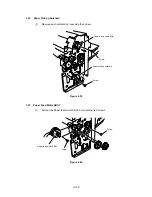
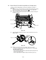
(3)
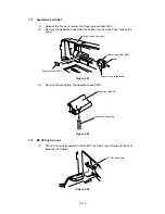
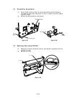
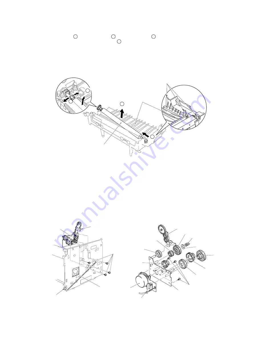
Open the transfer base hook and take off the left bearing (white) from the hook
(
A
). Lift the left side (
B
), slide it to the left (
C
) and take off the roller shaft from
the right bearing (black) (
D
).
(4)
Remove the transfer roller ASSY.
Caution:
Do not touch the sponge rubber roller when replacing the transfer roller (the
roller with hand grease or clasped too strongly may result in poor printing
quality).
Figure 4.58
1.30
DC Gear Holder ASSY
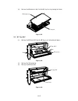
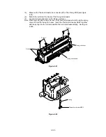
(1)
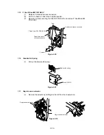
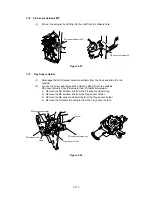
Remove the DC motor connector, then remove the Paper delivery holder spring.
(2)
Loosen the 4 screws and remove the DC gear unit from the chassis.
(3)
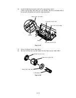
Remove the Paper delivery gear ASSY, the gears, the Gear 48 spring, and the
washer.
(4)
Loosen the 3 screws and remove the DC motor ASSY from the gear holder.
Figure 4.60
Figure 4.59
3 Hooks
Transfer roller ASSY
Transfer base ASSY
PS switch wire
Paper delivery
holder spring
4 screws
DC gear unit
Remote switch
Gear 28
DC gear holder ASSY
Gear 24/72
Washer
Gear 21
Connector
3 screws
Gear 39
Gear 20/50
Gear 48 spring
Gear 48
Paper delivery gear ASSY
Gear 22/55
DC motor ASSY
A
B
C
D
Содержание HL-2060
Страница 1: ...MECHANICS ELECTRONICS SERVICE MANUAL LASER PRINTER ...
Страница 41: ...III 8 A B F C D E 1 E 2 E 3 E 4 E 5 F Figure 3 7 Paper Feed Size SW PCB Circuit ...
Страница 129: ...VII 16 Test for memory MEMORY DISPLAY MEMORY DEBUG MEMORY TEST exit MENU ...
Страница 136: ...Appendix A 2 Paper Feed Size SW PCB Circuitry Diagram 1 1 CODE UK4067000 B512011 012 CIR NAME A 2 ...
Страница 137: ...Appendix A 3 Main PCB Circuitry Diagram 1 7 CODE UK4058000 B512006 CIR 1 7 NAME A 3 ...
Страница 138: ...Appendix A 4 Main PCB Circuitry Diagram 2 7 CODE UK4058000 B512006 CIR 2 7 NAME A 4 ...
Страница 139: ...Appendix A 5 Main PCB Circuitry Diagram 3 7 CODE UK4058000 B512006 CIR 3 7 NAME A 5 ...
Страница 140: ...Appendix A 6 Main PCB Circuitry Diagram 4 7 CODE UK4058000 B512006 CIR 4 7 NAME A 6 ...
Страница 141: ...Appendix A 7 Main PCB Circuitry Diagram 5 7 CODE UK4058000 B512006 CIR 5 7 NAME A 7 ...
Страница 142: ...Appendix A 8 Main PCB Circuitry Diagram 6 7 CODE UK4058000 B512006 CIR 6 7 NAME A 8 ...
Страница 143: ...Appendix A 9 Main PCB Circuitry Diagram 7 7 CODE UK4058000 B512006 CIR 7 7 NAME A 9 ...
Страница 144: ...Appendix A 10 Control Panel PCB Circuitry Diagram 1 1 CODE UK4077000 B512005 CIR NAME A 10 ...
Страница 145: ...Appendix A 11 Laser LD PCB Circuitry Diagram 1 1 CODE UK3253000 B48K253 CIR NAME A 11 ...
Страница 147: ...June 98 54T046NE0 HL2060 ...


