background image

6. Replacing Parts 


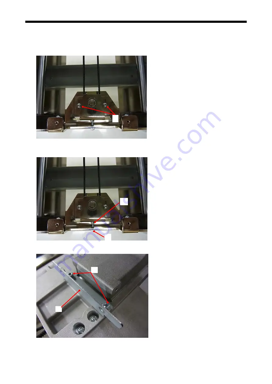
6-1-4. Platen Belt and Reduction Belt 

 
Replacing the Platen Belt 
Disassembling 

1.


Loosen the two Bolts Socket (S/P Washer) M4x14 (1).   


(1)

2.


Loosen the Nut 2 M4 (2) and loosen the Bolt Socket (3) for adjusting the tension.   


(3) 

(2)

3.


Remove two Bolt Sockets (4) and remove the Bellows Support Plate (5).   


(4) 

(5) 


GT-3 Series


128 

Содержание GT-3 Series

Страница 1: ...GT 3 Series Service Manual Please read this manual before making any adjustments GARMENT PRINTER GT 3 Series US suppo sa com Garmentprinters rt homepage http www brother u ...

Страница 2: ... to follow the instructions could result in death or serious injury CAUTION The instructions which follow this term indicate situations where failure to follow the instructions may result in minor or moderate injury Symbols This symbol indicates something that you should be careful of The picture inside the triangle indicates the nature of the caution that must be taken For example the symbol at l...

Страница 3: ...or electric shocks or problems with correct operation Immediately turn off the power switch and disconnect the power cord and arrange for a service call to resolve CAUTION Environmental requirements Use the printer in an area which is free from sources of strong electrical noise such as electrical line noise or static electric noise Sources of strong electrical noise may cause problems with correc...

Страница 4: ...o not touch the head heat sink as it may be HOT and may cause a burn Be careful not to get your fingers caught when closing the front cover otherwise it may result in injury to your fingers Do not move the Platen by hand The Printer may be mechanically and electrically damaged Do not disassemble the ink cartridge Disassembly assembly maintenance and inspection of this printer should only be carrie...

Страница 5: ...en removed or are difficult to read please contact your nearest Brother dealer 1 GT 3 Series iv 2 4 3 5 6 9 10 Watch your fingers or you may be injured 11 High temperature warning display 7 12 Be sure to connect the ground If the ground connection is not secure you run a high risk of receiving a serious electric shock and problems with correct operation may also occur 8 ...

Страница 6: ...Wash Liquid Grease Ink Cartridge Pretreatment 5kg Maintenance Solution 5kg Pretreatment 20kg Waste Ink Tank 0085Y GT 3 Series v ...

Страница 7: ... 7 Windows 8 41 2 5 7 Network Settings For Windows Vista Windows 7 Windows 8 42 2 5 7 1 Assignment of your computer s Address 42 2 5 7 2 Assignment of GT 3 s IP Address 45 2 5 7 3 GT 3 Setting on the LAN 47 2 5 8 Troubleshooting 54 2 5 8 1 Windows 7 Windows 8 will not recognize the GT 3 Printer Driver after you connect to your PC with USB cable 54 2 6 Preparation and Check before Use 60 2 6 1 Inst...

Страница 8: ...ten Top Plate and Shoulder Bar 147 6 1 11 Leveling of the Platen Top Plate 150 6 1 12 Carriage Motor 153 6 1 13 Carriage Driving Parts 155 6 1 14 Encoder Strip 158 6 1 15 Sensor Flap 162 6 1 16 Assembling Disassembling of the Maintenance Unit 165 6 1 17 Wiper Cleaner 171 6 1 18 Checking and Adjusting the Wiper Blade Assy 173 6 1 19 Pump Tube 178 6 1 20 Suction Pump Assy 183 6 1 21 Replace the Pump...

Страница 9: ...Sensor PCB Assy 339 6 2 20 Ink Switch PCB Assy 340 6 2 21 Lithium Battery 342 6 2 22 FFC 343 7 Transporting the GT 3 Series Required Maintenance for Long term Storage 346 7 1 Transporting the GT 3 Series 346 7 2 Required Maintenance for Long term Storage 350 8 Error Code List 354 8 1 Interpreting the Display 354 8 2 Warnings 354 8 3 Error Messages 356 9 Block Diagram of the Control Circuit 365 ...

Страница 10: ...4 F to 86 F 18 C to 30 C Humidity 45 to 85 no condensation Power supply Single phase100V 50 60 Hz JP 120 V 50 60 Hz US 230 V 50 60 Hz EU Oceania Power consumption 0 4 A average Ink cure Conveyor oven recommended 3 5 minutes at 160 C 320 F Head press 35 seconds at 180 C 356 F Time and temperature may vary depending on which manufacturer s dryer is used Pretreatment GT 361 GT 381 Pretreatment is nec...

Страница 11: ... Switch Turns on off your printer 8 Shoulder Bar Adjusts the T shirt position 9 USB flash drive Slot Inserts USB flash drive 10 Ink Cartridge Slots Load the Ink Cartridges of the appropriate color from the left side W1 W2 W3 W4 Black K Magenta M Cyan C Yellow Y 11 Ink Cartridge Storage Stores the new Ink Cartridges 12 Guard Bar Keeps the loading space of the Platens 13 Clearance Sensor Obstruction...

Страница 12: ... No Name Description 1 AC cord socket Inserts AC cord 2 USB port Inserts USB cable to PC 3 LAN port Inserts LAN cable to PC 4 Rear Cover Covers the Platen moving area 5 Waste Ink Tube Drains the waste ink Adjust the Tube length so that the Tube should go straight down into the tank without hitting the edge at the bottom 6 Waste Ink Tank Holds the waste ink Be aware of the room GT 3 Series 3 ...

Страница 13: ...cyan and yellow 2 Print Heads Back Jets the White Ink to the platen From the left W1 W2 W3 and W4 3 Filter Cover Fan Filter Exhaust Fan Absorbs ink mist inside the printer Exchange the Fan Filter inside the Filter Cover at the timing when you exchange Wiper Cleaner See 6 1 4 Replacing the Fan Filter in the Instruction Manual 4 Roller Felts Protects the roller by wiping off the surface Exchange the...

Страница 14: ...eaner and Cleaning the Caps Wipers in the Instruction Manual 4 Wiper Cleaner Front Color side 5 Wiper Cleaner Back White side Removes the waste ink on the Wiper Exchange regularly and keep them clean for print quality at the timing when you open the new ink cartridge or when you see the warning on the display of Control Panel Remove the projections of both sides and lift it up See 6 1 2 Replacing ...

Страница 15: ...the Platen height Left most position A is the normal T shirt position Check the exact height with Platen Button on Control Panel when you print on thicker material The adequate clearance between the Flap Sensor and the printed material is app 2 mm See 4 5 Placing the T shirt on the Platen in the Instruction Manual Ink mist may spreads inside the printer If you print with wider clearance the ink mi...

Страница 16: ...eaning Returns to Standby mode 6 Up Button Selects the previous upper item Increases a numeric value Opens the Menu display 7 Down Button Selects the next lower item Decreases a numeric value Opens the Menu display 8 OK Button Executes the selected command Opens the Menu display Clears the error status 9 Back Button Returns to the previous display Opens the Menu display 10 Display Displays the Job...

Страница 17: ...aten Size set by Printer Driver 5 Number of Platen Move Shows the number of the Platen Move loading unloading in printing one print data 6 Number of Print Shows the number of prints completed of the print data 7 Printer Status Shows the printer status 8 Amount of Ink Remained Shows amount of ink remained in each cartridge from the left W1 W2 W3 W4 Black K Magenta M Cyan C and Yellow Y It flashes w...

Страница 18: ...ts Uni directionally Always Bi Directional always prints bi directionally See 7 2 4 Changing the Print Direction in the Instruction Manual Maintenance Goes into the Maintenance submenu White Tube Cleaning Cleans the pigment in White Print Heads and Tubes See 4 1 4 Cleaning the Tubes and Print Heads White Color Tube Cleaning Load White Loads White Ink into the Tubes filled with Maintenance Solution...

Страница 19: ...k in printing See 7 2 10 Adjusting the Flushing Interval in the Instruction Manual Flushing Volume Adjusts the ink volume in flushing See 7 2 11 Adjusting the Flushing Volume in the Instruction Manual Daily Cleaning W Setting Adjusts the amount of White Ink that is flushed in Daily Cleaning White See 7 2 12 Adjusting the amount of White Ink in Daily Cleaning White in the Instruction Manual Auto Jo...

Страница 20: ...ded for print quality 3 Never use an extension cable 4 A working space must be left around the printer Minimum space of 100 cm 39 4 inch on the front and the right Keep away from the right side of the Exhaust Fan at least by 20 cm 7 9 inch 5 The body size is approximately 137 cm 104 5 cm 66 cm 53 9 41 1 26 0 and the weight is approximately 111 kg 245 lb 6 The table that supports the printer should...

Страница 21: ... sure to use this to make the surface smooth and flat in curing the Pretreatment and Ink especially with White Ink Urethane mat continuous foam Use this to release the hot air quickly in curing Pretreatment T shirt printed material Cotton 100 Light colored polyester mixed cotton cotton should be 50 or more Dark colored polyester mixed cotton cotton should be 70 or more Note Some manufacturing bran...

Страница 22: ...tenance Cleaning Kit SB3168 Nozzle Cleaning Kit SB3082 Wash Liquid SA6248 Options Parts Code Middle platen 14x16 SB3105 Platen Sheet SB3035 Youth Platen 10x12 SA6399 Platen Sheet S SA6401 Baby Platen 7x8 SA8213 Platen Sheet SS SA8211 Pretreatment Roller SB1290 Waste Ink Tank SB2582 Maintenance Cartridge W SB3264 Maintenance Cartridge Color SB3265 Filter Cartridge W SB2512 Filter Cartridge Color SB...

Страница 23: ...Unpacking Procedure Unpack the printer by following the steps 1 to 8 Note Do not turn ON the printer until you finish the steps 2 2 4 Removing protection material or the printer may be damaged by unexpected motion Accessories 0176Y 14 GT 3 Series ...

Страница 24: ...tely 111 kg 245 lb Transporting and setting up of the printer should be held in proper way The machine may fall down and cause injury GT 3 Series 15 When transporting and installing the printer put your hands in the positions as shown in the illustration 0019N Positions where you must not lift 0020N ...

Страница 25: ...tely submerged in the waste ink Be sure that the tube should not fold or bend Failure to follow the precautions above can negatively impact the printing quality by causing an increase in the internal tube pressure Sometimes the waste ink may overflow inside of the printer by restricting the waste ink flow 0162Y 2 2 4 Removing protection materials Make sure to remove protection materials before sta...

Страница 26: ...ning Removal Remove the Cushioning 2 from the Ink Cartridge Storage Rack 1 Separate the Cushioning in two pieces GT 3 Series 17 0164Y 0163Y 2 Flatten and tilt it to pull it out 0166Y 3 Follow the same steps for the other piece 0167Y ...

Страница 27: ...he four nuts 3 of the Adjusters 2 at the bottom of the Main Frame 2 3 2 3 3 Rotate the Adjusters 2 to adjust the levelness in the lateral direction by less than 1 mm Rotate the Adjuster CLOCKWISE to raise the printer Rotate the Adjuster COUNTERCLOCKWISE to lower the printer Note Adjust the adjuster 2 within 32 mm See the image below 32 mm or shorter 2 3 0022N 18 GT 3 Series ...

Страница 28: ...inter The Waste Ink Tube should be mounted properly straight without touching the bottom of the Waste Ink Tank Parts Code is in 2 1 4 Consumable Requirements and Options The Rear Cover Cover PB should be mounted The space should be at least 30 cm in the front for Platen moving forward at least 20 cm in the right for air flow from the Exhaust Fan The strap that fixes the Carriage should be removed ...

Страница 29: ... Band for safety operation Touch the metal area of the printer e g covers to reduce the static electricity 5 Remove the plastic cover on the Carriage PCB Disconnect the white cable left and remove the four claws on the both edges right 6 Remove the silicone tubes that are attached the screws under the Carriage PCB left and remove the holes of the cover right and remove the plastic cover To Center ...

Страница 30: ...at the back of the mounting position 9 Hold the knob of the Print Head 3 left and push it downward so that the V shaped groove can fit the inside of the Positioning Pin 2 Push down the Print Head to fix the corner of the Print Head by the Flat Spring 4 right 1 Nozzle surface 2 2 4 5 10 Rotate the Lever to fix the Print Head 2 4 3 Slide the Print Head into the Flat Spring from the right to the left...

Страница 31: ...eft insert straight into the connector and fix it by pushing the tabs of both sides right Important Do not insert the Flat Cable at an angle in installation The electric current may not be stable and increase the Print Head temperature which causes machine errors e g Head Temp High mis firing and give serious damage to the Print Head Do not repeat the insertion or the terminal metal may be damaged...

Страница 32: ...e of the Tube Tube White FFCs NEVER stay this area White FFCs must go through the inside of the Tubes If outside of the Tubes then the Tubes may touch the other parts while Carriage moving and should get seriously damaged Color Tubes Note The photos above are all for GT 381 Mount only on CMYK for GT 341 mount on CMYK plus W1 W2 for GT 361 White Connectors K M C Y W4 W3 W2 W1 FFCs area W4 W1 W2 W3 ...

Страница 33: ...r so that the fold at the back should cover the metal plate under the Carriage PCB 16 Put the two screws through the holes on the front side of the Plastic Cover left and apply the silicone tubes to the screws that were removed in the step 6 17 Put the claws on the Plastic Cover removed in the step 5 left and finally connect the Harness 18 Push the Stop Lever to release the lock when you close the...

Страница 34: ...ed on with Administrator rights on the PC 1 Turn on your PC 2 Close all open applications 3 Insert the Install CD included to your PC Open the CD ROM drive and double click Setup exe 4 The Installer starts installation Follow the indications of the dialogs Note When you install to the PC that the printer drivers and tools are already installed e g updating the message to confirm uninstallation app...

Страница 35: ...wer OFF Note We do not recommend connection via a USB hub to the printer 2 Connect the other end of the USB 2 0 Cable to your PC 3 Turn on your GT 3 printer The following window appears Select No not this time and then click Next 4 Insert the Install CD The following window appears Continues to the next page GT 3 Series 26 ...

Страница 36: ...ect GT 3 gpd in 32bit_OS the folder and then click OK The installation continues 6 Click Finish when Completing the Found New Hardware Wizard dialog 7 Open Printers and Faxes in Control Panel 8 Click either Brother GT 3 Brother GT 3 FileOutput icon and select Set as Default Printer on File menu This will help to do the layout with your application software The PC setup is now completed Note for in...

Страница 37: ...s XP 2 5 4 1 Assignment of your computer s IPAddress Note Jump to 2 5 4 2 Assignment of GT 3 s IPAddress if you r PC has already been assigned IP address 1 Select Network and Internet Connection in the Control Panel 2 Select Network Connection GT 3 Series 28 ...

Страница 38: ...2 Setting up GT 3 Series 3 Select LocalArea Connection 4 Click the Properties Button GT 3 Series 29 ...

Страница 39: ...ries 5 Select Internet Protocol TCP IP and click the Properties Button 6 Assign the defined number of IP address Subnet mask and Default gateway to your PC and click OK button The numbers below are examples GT 3 Series 30 ...

Страница 40: ...computer s IP address 1 Turn ON the GT 3 with your PC and GT 3 are connected with USB 2 0 cable Execute the GT 3 Maintenance and select IP addressAssignment Click the Next Button 2 Assign the defined number of IP address Subnet mask and Default gateway to GT 3 and click OK button The numbers below are examples GT 3 Series 31 ...

Страница 41: ...ies 3 IP address is successfully assigned to GT 3 4 The error dialog appears if some irregular numbers are assigned as IP address in the step 2 Subset mask or Default gateway Confirm the numbers and re enter GT 3 Series 32 ...

Страница 42: ...3 Series 2 5 4 3 GT 3 Setting on the LAN 1 Connect your PC with GT 3 with LAN cable and turn ON the printer Select Printers and Faxes and select File Add Printer 2 The Wizard starts Click the Next Button GT 3 Series 33 ...

Страница 43: ...ting up GT 3 Series 3 Select the Local printer attached to this computer and click the Next Button 4 Select Create a new port and Standard TCP IP Port as the Type of port Click the Next Button GT 3 Series 34 ...

Страница 44: ...Setting up GT 3 Series 5 The Wizard starts Click the Next Button 6 Input the IP address that you assigned in the Step 2 of 2 5 4 2 Assignment of GT 3 s IP Address and click the Next Button GT 3 Series 35 ...

Страница 45: ...ng Add Standard TCP IP Printer Port Wizard Select Custom in the Device Type and click the Settings Button 8 Select LRP in Protocol input BINARY_P1 in Queue Name of LPR Settings and click the OK Button 9 The Wizard will soon go back to the Step 7 above Click the Next Button GT 3 Series 36 ...

Страница 46: ... Series 10 Add Standard TCP IP Printer Port Wizard is finished Click the Finish Button 11 The dialog goes back to the Add Printer Wizard and the Install Printer Software starts Click the Have Disk Button GT 3 Series 37 ...

Страница 47: ... Browse Button and select the 32bit_OS folder in the Installer and then click the OK Button Only 32 bit OS is available for Windows XP 13 Confirm that Brother GT 3 should be selected in the Printers and click the Next Button GT 3 Series 38 ...

Страница 48: ...g shows Set as Default Printer better to select GT 3 File Output Printer Driver as Default Printer Share name Not shared and Test Page No and click the Next Button 16 The final dialog appears to show that GT 3 has successfully added to your PC Click Finish Button to finish the Wizard GT 3 Series 39 ...

Страница 49: ...nter Connect with USB 2 0 Cable first and then connect to the LAN by following the steps in this Instruction Manual Install File Output Printer Driver Brother GT 3 FileOutput first to your PC Do not connect the printer to the PC at this stage Note You must be logged on with Administrator rights on the PC 1 Turn on your PC 2 Close all open applications 3 Insert the Install CD included to your PC Op...

Страница 50: ... Cable for Windows Vista Windows 7 Windows 8 1 Connect the USB 2 0 cable to your printer power OFF 2 Connect the other end of the USB 2 0 Cable to your PC 3 Turn ON your GT 3 printer Installation starts automatically The information appears at the right bottom of the PC monitor 4 After installation open Printers in Control Panel of PC 5 Click either Brother GT 3 or Brother GT 3 FileOutput icon and...

Страница 51: ... IPAddress if you r PC has already been assigned IP address 1 When your PC has not been assigned IP address connect your PC to the Network with LAN cable first and then select Network and Internet and select Network and Sharing Center 2 Select View status in the LocalArea Connection where you are going to assign the IP address Windows 8 Connection e g Ethernet GT 3 Series 42 ...

Страница 52: ...2 Setting up GT 3 Series 3 Click the Properties Button 4 The following caution appears when UserAccount Control is ON Select Continue Button to go next GT 3 Series 43 ...

Страница 53: ... Select Internet Protocol Version 4 TCP IPv4 and click the Properties Button 6 Assign the defined number of IP address Subnet mask and Default gateway to your PC and click OK button The numbers below are examples GT 3 Series 44 ...

Страница 54: ...nish assigning your computer s IP address 1 The following caution appears when UserAccount Control is ON Select Allow Button to go next 2 Turn ON the GT 3 with your PC and GT 3 are connected with USB 2 0 cable Execute the GT 3 Maintenance and select IP addressAssignment Click the Next Button GT 3 Series 45 ...

Страница 55: ...ult gateway to GT 3 and click OK button The numbers below are examples 4 IP address is successfully assigned to GT 3 5 The error dialog appears if some irregular numbers are assigned as IP address in the step 3 Subset mask or Default gateway Confirm the numbers and re enter GT 3 Series 46 ...

Страница 56: ...3 with LAN cable and turn ON the printer Windows Vista Select Printers from the Control Panel Windows 7 Select Devices and Printers from the Control Panel Windows 8 Select View devices and printers from the Control Panel Select Add a printer 2 Select Add a local printer GT 3 Series 47 ...

Страница 57: ...P Port as the Type of port Click the Next Button 4 Input the IP address that you assigned in the Step 3 of 2 5 7 2 Assignment of GT 3 s IP Address and turn OFF the check box Query the printer and automatically select the driver to use Click the Next Button GT 3 Series 48 ...

Страница 58: ...es 5 The following Detecting TCP IP Port dialog appears and then it changes automatically to Add Printer 6 The message The device is not found on the network appears Select Custom and click the Settings Button GT 3 Series 49 ...

Страница 59: ...2 Setting up GT 3 Series 7 Select LRP in Protocol input BINARY_P1 in Queue Name of LPR Settings and click the OK Button 8 The Wizard will soon go back to the Step 6 Click the Next Button GT 3 Series 50 ...

Страница 60: ...back to the Add Printer and the Install Printer Software starts Click the Have Disk Button 10 Click the Browse Button and select either 32bit_OS or 64bit_OS folder in the Installer depending on your PC and then click the OK Button GT 3 Series 51 ...

Страница 61: ... Printers and click the Next Button 12 Select Replace the current driver and click the Next Button 13 The dialog shows Printer Name Set as Default Printer better to select GT 3 File Output Printer Driver as Default Printer Share name Not shared Click the Next Button GT 3 Series 52 ...

Страница 62: ...2 Setting up GT 3 Series 14 The final dialog appears to show that GT 3 has successfully added to your PC Click Finish Button to finish the Wizard GT 3 Series 53 ...

Страница 63: ...imes regard GT 3 as an Unspecified Device If this is the case you can see the error message at the right bottom of your desk top The icon and message may differ depending on your Windows version Left Click on Click here for details in the pop up window The following window appears Close out of it to continue the installation Open the Control Panel and click on the Devices and Printers icon You wil...

Страница 64: ...es How to recover 1 Open the Control Panel and select Devices and Printers icon Select and Right Click on the Garment Printer GT 3 in the Unspecified category and left click on Properties in the drop down menu GT 3 Series 55 ...

Страница 65: ...l be displayed Click the Hardware tab and select the Brother GT 3 in the Device Functions list Then left click on the Properties button on the bottom right 3 The following GT 3 Properties window will appear Left click on the Change settings button on the left bottom 56 GT 3 Series ...

Страница 66: ...nitor Sometimes the position of the Dialog may shift Click the Driver tab in the redisplayed window Then click the Update Driver button You would not be able to click the Update Driver button on the Driver menu in the previous screen because it is invalid there Click the OK button 5 Click Browse my computer for driver software when the following window appears GT 3 Series 57 ...

Страница 67: ...s 32 bit OS Click the Next button to continue Note When you install the downloaded Printer Driver Web version the folder names are as follows select the necessary folder GT 3 GT3Setup GT 782 GT782 Setup_32bit or GT782Setup_64bit GT 541 GT541 Setup_32bit or GT541Setup_64bit 7 The installation of printer driver will start After a while the following window appears The following screen appears when W...

Страница 68: ...on to confirm that GT 3 is successfully installed in the Printers and Faxes category If that window is kept open while updating select View and Refresh to update the contents of the written window 9 The Brother GT 3 Printer Driver has been successfully recognized as a printer GT 3 Series 59 ...

Страница 69: ...tenance Required for Long term Storage 2 Replacing the Ink Cartridge The ink indicator on the Display flashes when the Ink Cartridge is getting low Prepare the new Ink Cartridge option and replace it when Empty XXXX color is displayed See 2 1 4 Consumable Requirements and Options for part code 1 Open the new Ink Cartridge Note Pigments in the White Ink are sinking little by little all the time Hol...

Страница 70: ...dge Replace the Maintenance Parts packed together with Cyan Ink Cartridge 380 cc 180 cc Magenta Ink Cartridge 380 cc and White Ink Cartridge 380 cc when you open the new one Clean the Caps and Wipers replace the Wiper Cleaners Fan Filter Roller Felts 4 Flushing Plate Sponge top and Flushing Plate Felt bottom according to our maintenance schedule to maintain good print quality Replace them when you...

Страница 71: ...nance solution 2 Pour about 25 ml of fresh Maintenance Solution 2 into the Bottle 1 about half way between the bottom and the first line on the scale 1 2 4725M 3 Tilt the Bottle 1 and rotate it about three times as shown in the illustration so that the Maintenance Solution 2 flows around the base and sides inside the bottle to clean them Note If you shake the Bottle with Maintenance Solution bubbl...

Страница 72: ...press OK Button 0193Y 13 The pump starts turning and the Maintenance Solution will be installed to the Tube It takes approx 50 seconds to introduce the Maintenance Solution 14 After filling the Maintenance Solution the message Insert Ink Cartridge is indicated on the Display Remove the Maintenance Cartridge and insert the well agitated White Ink Cartridge to W1 slot Confirm the agitation by referr...

Страница 73: ...r slots 3 Select Maintenance Initial Cleaning from the menu and load the ink 4 Select the color that you are going to install the Ink Select All Colors to install the four Color Inks in one time The printer will install one by one it takes about 50 seconds to install one color The pong sound rings and the installation for W1 is finished successfully 5 Select the color one by one when you install o...

Страница 74: ...paper clear plastic plate etc 2 Set the Platen height to the A position 3 Place a sheet of paper A4 or letter size at the right corner of the Platen 1 as shown below Use adhesive tape to make the paper flat You can use a T shirt instead of paper 1 0081Y 4 Select Test Print with the Up Down Button from the menu and then press the OK Button 5 Press the Up Down Button to select either Nozzle Check CM...

Страница 75: ...1 two in W2 have the problem The Print Heads need to be cleaned better to execute All Whites See 2 6 4 Head Cleaning Note GT 3 has multiple White Print Heads 4 on GT 381 2 on GT 361 and mis firing is not so severe compared with the one with CMYK Print Heads See the left print result on paper and some of the nozzles are not fired but the actual print quality on the right print on pretreated T shirt...

Страница 76: ... to either Stand By or Ready when the Head Cleaning is finished Normal Powerful Cleaning 1 Make sure your printer is either Standby or Ready mode 2 Select Head Cleaning from the menu and press the OK Button 3 Press the Up Down Button to select Head Cleaning and then press the OK Button Select either Normal Cleaning or Powerful Cleaning by Up Down Button and press the OK Button Refer to the steps i...

Страница 77: ...k paper in executing White Print Head adjustment 2 Prepare a PC that GT 3 Printer Driver is installed where the GT 3 Maintenance Tool is in Brother GT 3 Tools Procedures 1 Confirm that the PC and the GT 3 Series printer is connected by USB cable directly This operation cannot be done via a print server 2 Turn ON the printer If the Printer Driver installation has been started be sure to complete th...

Страница 78: ...s of prints before adjustment made at Step 3 The pattern 2 print result exhibits no checkerboard appearance and is the smoothest Furthermore the left vertical bars are also displaced in the up and down directions Look at the print result for all colors and enter the number of the pattern that appears to be the most uniform In the above print result for example 2 in position K is the best Check the...

Страница 79: ...ble adjustment will be complete for that combination of Platen and Print Head The example below shows a good print result 9 The example below shows a bad print result If the pattern is uniform at numbers other than 4 to 6 the printed image is displaced in the up down left or right directions The Platen height may be too low and 2 right vertical bars are visible readjustment is necessary Check whet...

Страница 80: ...is selected Perform the adjustment procedure in the same way for the remaining combinations of Print Head and Platen Return to Step 4 if NO is selected Enter the previous print results again follow the dialog instructions perform a test print and then check the result At Step 6 repeat the adjustment until the conditions allow YES to be selected 11 The adjustment of all four Print Heads is complete...

Страница 81: ... shirt 2 Apply pretreatment solution to the cloth and then secure on the printer Procedures 1 Confirm that the PC and the GT 3 Series printer is connected by USB cable directly This operation cannot be done via a print server 2 Turn ON the printer If the Printer Driver installation has been started be sure to complete the installation by the proper procedures See 2 5 Preparing your PC 3 Execute GT...

Страница 82: ...d on the dialog and print the test pattern again and check if the adjustment has been done successfully If the center square X axis coordinate 0 Y axis coordinate 0 is completely black with no white lines this shows that the alignment has been done correctly Adjustment is now complete for this Platen The example below shows a good print result 6 73 GT 3 Series ...

Страница 83: ...Re adjust button that appears The adjustment is complete when you select YES The menu returns to Step 3 if NO is selected Enter the previous print results again follow the instructions on the dialog print a test pattern and then check the result At Step 5 repeat the adjustment until the conditions allow YES to be selected The procedure is complete when the following dialog appears 74 GT 3 Series ...

Страница 84: ... Do not move the Platen by hand The Printer may be mechanically and electrically damaged Do not put your hands inside the covers while the printer s power is turned on otherwise your hands may touch against moving parts and this may result in injury 3 1 Menu 3 1 1 User Menu Advanced Menu There are two types of menu in the printer User Menu and Advanced Menu service only User Menu is for operators ...

Страница 85: ...est White Center top of 14x16 Confirms the position of the damaged Print Head s 3 1 2 2 Maintenance Parts Exchange The regular maintenance e g cleaning the inside and replacing the Maintenance Parts are necessary to keep the printer in good conditions Poor maintenance will surely cause serious issues for example the printed materials may be spoiled by dirty waste ink poor print quality may produce...

Страница 86: ...te Tube Cleaning Checking and replacing the Tubes Checking the inside of Print Head Color Tube Cleaning Checking and replacing the Tubes Checking the inside of Print Head 3 1 3 How to go to Advanced Menu The following steps show how to go to the Advanced Menu Do not release these functions to customers 1 Confirm the printer is either Standby or Ready not in operation 2 Press any one of the OK Up D...

Страница 87: ...5 3 Output Check This menu can operate some of the movable parts individually to confirm the output function of the printer The following menu is identical for all models you can even activate the Solenoid Ink Ret_W Assy on the GT 341 No Menu Description 1 Cap Test Moves up and down the Caps on the Maintenance Unit 2 Wiper Test Moves back and forth the Wipers on the Maintenance Unit 3 Carriage Tes...

Страница 88: ... confirm the Print Head clogging caused by cracked Tube You can confirm the banding issue with this pattern Refer to 4 1 2 Heavy misfiring in printing Checking Cracks inside the Tube The Solid Print pattern is printed almost the full size of 14x16 Platen Bette to print on T shirt rather than on paper because the ink volume is large and may cause flood on the paper Example Solid K for Black 3 1 5 7...

Страница 89: ... to rotate Confirm the Maintenance Solution inside the Cap if it is absorbed into the Maintenance Unit then the Waste Ink Tubes will be fine If you find the Maintenance Solution will not be absorbed not move the surface then the Waste Ink Tube may be clogged or the Tube Pump may malfunction How to check the Pump 2 1 Prepare a jig as shown in the photo to confirm the performance of the Pump Tube Co...

Страница 90: ...nt by the head pressure 5 4 5 4 Select the color you are going to confirm and press the OK button 5 Weight the Bottle after the menu is finished The Tube Pump works properly if the current weight is decreased by approx 38g from the original The Waste Ink Tubes may be clogged if the current weight is decreased by less than 30g from the original Or the Tube Pump may not work properly Confirm the ins...

Страница 91: ...h USB Flash Drive 3 2 2 How to Update from USB Flash Drive 1 Copy the firmware data GT3FIRM bwf on the root folder of the USB Flash Drive Do not copy more than 10 versions in one USB Flash Drive or the firmware data files will not be indicated on the Display 2 Insert the USB Flash Drive to the printer and select Firmware Update in the Advanced Menu 3 Select the file name you are going to update an...

Страница 92: ...date is finished 3 2 3 3 Update with Boot System program The Boot System program works when the update fails by unexpected situations and the Main program will not work properly The Boot System program temporarily reads the firmware data in the USB Flash Drive and start the operation of GT 3 Follow the steps below and re update the firmware 1 Prepare the previous version of firmware one version do...

Страница 93: ...2 Insert the USB flash drive and turn ON the printer with pressing the Print Button 3 Keep pressing the Print Button until the initial dialog logo is indicated on the Display and the printer will boot with the firmware GT3FIRM bwf in the USB flash drive and then the issued program will be overwritten 4 After the printer is successfully initialized remove the USB flash drive and turn OFF and then t...

Страница 94: ...egardless of the language selected when installing the printer driver However the screen is displayed in Japanese only on PC s running on a Japanese Windows version 3 3 2 Resetting Clean Tube W Warning It is necessary to clean white ink tubes approximately once a week Refer to 5 1 3 White Ink Maintenance for details of white ink maintenance A Clean Tube W is a value from 1 to 4 with GT 381 1 or 2 ...

Страница 95: ...itches to Off line Demonstration Mode to allow the tool functions and specifications to be checked Normal file name GT3ServiceTool exe File name in demonstration mode DemoGT3ServiceTool exe 3 4 Getting Log File and Analysis 3 4 1 Precautions of getting Log File The way to get Log file from the GT 3 printer is to select Log copy to USB of the menu of the printer and write the Log File to USB flash ...

Страница 96: ... data is being saved to the USB flash drive while the Print Button is blinking Wait for a while after the Print Button stops blinking and the printer bells 5 Make a copy of the log file saved in the USB flash drive and send it to the technical service Note Do not touch the USB flash drive while the Print Button is flashing it may destroy the saved data 3 4 3 View Log File with GT 3 Service Tool Pr...

Страница 97: ...lect the Buttons so you can view the log file from different viewpoint Note The time recorded in the Log file is by the internal clock inside the GT 3 Series The time may be shifted from the real operation time 4 Click Finish and then the GT 3 Service Tool is closed 88 GT 3 Series ...

Страница 98: ...ht between the platen or the T shirt tray and the covers it may be injured Wait at least 1 minute after turning off the power switch before opening the front cover Do not touch the head heat sink as it may be HOT and may cause a bum Be careful not to get your fingers caught when closing the front cover otherwise it may result in injury to your fingers Do not move the Platen by hand The Printer may...

Страница 99: ... Turn OFF ON Electrical Check Electrical Check Check ink in cap just after moving pump and waste ink tubes Better Increase humidity Solid YES Increase wipe in printing Do Normal HC Print Nozzle CP While printing Almost no misfiring 1 out of 4 or almost none Nozzle CP 印刷 Do Normal HC Print Nozzle CP for several times Dried Air inside Wait 10 min missing band Better after OFF ON misfiring Filter War...

Страница 100: ...ed in the cap or not If not clean the Waste Ink Tubes of Maintenance Unit Refer to 6 1 16 Assembling Disassembling of the Maintenance Unit and 6 1 19 Pump Tube The following check items are not related to misfiring on Print Heads other than the problematic Print Head being investigated The print condition may become faint at both edges if the GT 3 is installed in an extremely dry location Refer to...

Страница 101: ...folded or damaged Is there any peeling at the edges Replace the FFC Has the Wiper Blade come off Remove the Wiper Cleaner and check if the bottom of the Wiper Blade moves when the top is pushed If it moves the Wiper Blade has come off Check for any looseness or bending at the Tube and Head connections Check if the Wiper Cleaner Cassette is dirty and replace with a new one if required NO NO YES Go ...

Страница 102: ...es firing Problem solved No PH replacement NO YES NO NO YES NO YES Tube Cleaning All nozzles firing Print check pattern after reconnecting FFCs Max 25 cc of ink used Execute Powerful cleaning up to 10 times Are FFCs connected properly All nozzles misfiring All nozzles firing From previous flow Go to Flow 4 No PH replacement Problem solved Repeating Powerful cleaning 10 times does not resolve the p...

Страница 103: ... not resolve the problem All nozzles firing Max 25 cc of ink used The fixed nozzle is still misfiring Replace the Print Head 10 cc of ink used Clean the nozzle surface and install ink again Execute Powerful cleaning up to 10 times Clean the Wiper and Print Head Cap Replace the Wiper Cleaner The Print Head may leak Replace the Print Head Is the same nozzle s always misfiring Wipe the Nozzle with Cl...

Страница 104: ...y may not be measured correctly NO Print a solid pattern on A3 paper after Powerful Head cleaning Exchange Filter YES Print a check pattern and count the number of misfiring nozzles Straighten the Tube execute Powerful cleaning and then print a solid pattern Significant misfiring immediately after printing started Significant misfiring immediately after printing started Tube clogging Replace Print...

Страница 105: ...ube Pump Tube and check the connection between the Tubes Connection OK All nozzles firing Faulty Solenoid Max 12 5 cc of ink used Execute Powerful head cleaning up to 5 times There is no problem with the Maintenance unit Procedure 1 Remove ink in the Print Head Cap 2 Execute Powerful cleaning 3 Suction OK if ink remaining in Print Head Cap If not issue is in Tube Pump Open the Rear Cover DB and re...

Страница 106: ...cement NO Loose connection of Tubes and Joints YES YES NO All nozzles firing Execute Initial cleaning until the air bubbles should go into the PH Wait 10 minutes to remove air Execute Powerful cleaning and print Nozzle CP Problem solved No PH replacement Up to 10 times Max 25 cc of ink used YES NO All nozzles firing Replace the Print Head GT 3 Series 97 ...

Страница 107: ...raph below As the paper absorbs ink it will curl up and contact the Print Heads This should be prevented by adjusting the Platen height to position C Use adhesive tape at corners and edges to make the paper flat 2 Load the solid print pattern to the printer from the Advanced Menu Display the Advanced Menu from the left Operation Panel to check the color Tubes and from the right Operation Panel to ...

Страница 108: ...ilter Life expired 1 Replace the Filter of the issued Print Head Refer to 6 1 33 Replacing the Filter on the Print Head 2 If the issue recurs after replacing the Filter to new there may be high possibility of ink gel caused by Tube cracks Replace the Tube by referring to 6 1 35 Tubes C Print Head issue Replace the Print Head that has an issue Refer to 6 1 33 Replacing the Filter on the Print Head ...

Страница 109: ...ter Setting Flushing Interval in the menu 11e0035Y 2 Select one of the four Every 52 lines Under very high humid condition if you reduce the print time Every 40 lines Default and standard setting Every 20 lines Try this setting wipe double than the standard setting Every 10 lines Wipe every 10 lines most effective but the print time will be the longest 11e0036Y 3 Press OK button and then the Displ...

Страница 110: ...king and replacing the Tubes Checking the inside of Print Head Color Tube Cleaning Checking and replacing the Tubes Checking the inside of Print Head When you execute White Color Tube Cleaning be sure to use the clean bottle and fresh Maintenance Solution follow the steps below when you fill in the bottle Clean the inside regularly 1 Throw away the old Maintenance Solution 1 left in the bottle 2 P...

Страница 111: ...ance Cartridge Note If you leave GT 3 printer unused for more than two weeks execute White Tube Cleaning for storage Insert Capping Cartridges option in place of White Ink Cartridge See 7 2 Required Maintenance for the Long Storage All Whites Tube Cleaning Sequence of All Whites Tube Cleaning firmware ver 2 10 or higher 102 GT 3 Series Note If you execute Tube Cleaning one by one then the first Re...

Страница 112: ...ted on the Control Panel Uncap open the air in cap and press OK button The air goes into the tube and washes away the remained White Ink It takes about 10 minutes to wash one tube 0194Y 9 After washing with air bubbles when the peep sounds ring the message Insert Filter Cartridge is indicated on the Control Panel Remove the Maintenance Cartridge of the W1 position and insert the Filter Cartridge a...

Страница 113: ...g of the White Ink starts from loading Maintenance Solution to load White Ink into the Tube smoothly After Tube Cleaning when the Tubes are filled with Maintenance Solution select Load White to load White Ink One by one Tube Cleaning 1 Fill the bottle with Maintenance Solution Confirm that at least more than 250 ml per one Print Head is in the bottle 2 Confirm in advance the amount of the Waste In...

Страница 114: ...ed and insert Color Filter Cartridge Select Maintenance and Color Tube Cleaning select the Print Head to be replaced and press the OK Button The ink will be flushed 4 Clean the Tube and the Print Head with the Maintenance Solution Remove the Color Filter Cartridge and insert Color Maintenance Cartridge Fill the Bottle with the Maintenance Solution of 250 ml or more and insert the Tube to the botto...

Страница 115: ... start operating and injury could result Inspection adjustment or maintenance Replacing parts such as print heads or wiper blade Wait at least 1 minute after turning off the power switch before opening the front cover Do not touch the head heat sink as it may be HOT and may cause a burn Be careful not to get your fingers caught when closing the front cover otherwise it may result in injury to your...

Страница 116: ...liquids Ink Wash Liquid Maintenance Solution Pretreatment or waste liquid under any circumstances as they can cause vomiting and diarrhea Keep the liquids out of the reach of children Be sure to wear protective goggles and gloves when handling the grease so that they do not get into your eyes or onto your skin If the grease gets into your eyes or onto your skin inflammation can result Furthermore ...

Страница 117: ...to exchange Wiper Cleaners after you clean the Caps and Wipers which is packed together in Maintenance Cleaning Kit 1 Remove the Wiper Cleaner Refer to 6 1 17 Wiper Cleaner 2 Prepare the Maintenance Cleaning Kit Option See 2 1 4 Consumable Requirements and Options to get the Code Number 0062Y 3 Wear the gloves and wet both sides of a Clean Stick green grip with the Wash Liquid Note Use only the Wa...

Страница 118: ... Cap Note Do not use dry Clean Stick it cannot clean ink or dust It may damage the Print Head Caps Wipe off the dirty ink of Clean Sticks with soft cloth if it is too dirty and wet with Wash Liquid 0065Y Note The Warning Exchange Maintenance Parts is indicated by counting the number of Head Cleaning Nozzle may be dried by being left uncapped Execute Normal Head Cleaning for all Print Heads and con...

Страница 119: ... Up Down Button from the menu and press the OK Button The Platen will be loaded and the Carriage and the Wipers will be moved to the cleaning position The following message appears 08e0033Y 4 Turn off your printer 5 Open the Front Cover with both hands until it is locked with the stopper Open the Nozzle cleaning Kit Put on the gloves and wet a Clean Applicator white grip with round form with full ...

Страница 120: ...e Pay attention not to touch or stain the Clearance Sensor in cleaning W3 and W4 2 Clearance Sensor 7 Check and clean around the Caps and Wipers You can use both Clean Applicator round form with white grip and Clean Stick flag form with green grip See 5 1 1 Cleaning the Print Head Caps and Wiper Blades Wipe off the edges of the Flushing Plate the front back of the Clearance Sensor and around the P...

Страница 121: ...artridge hold the cartridge with both hands upside down from the mounted position and shake by moving back and forth to mix up the pigment in the bottom and shake it horizontally in 30 seconds to 1 minute 2 Select Daily Cleaning White from the menu and press the OK Button Select All White to do in one time or select the each Print Head to do one by one Press OK button to continue 3 After replacing...

Страница 122: ...se option to the gear of the CR motor if the printer causes CR errors After applying be sure to adjust the CR Speed from the menu 5 1 5 Cleaning the Encoder Strip There must be some dust and mist covering the Encoder Strip to cause reading error when some error occurs during the printing operation Clean the Encoder Strip with the attached tool 1 Prepare the Encoder Cleaner and ethanol of 95 or hig...

Страница 123: ...eaner 3 0073Y Note Use ethanol of higher purity 95 or higher one is recommended to remove the dust smoothly and easily without giving damage to Encoder Strip and not to leave any chemicals on the surface 9 Push the position A shown below with your finger to give space between the felts 0074Y 10 Put the Encoder Cleaner to the Encoder Strip so that the Encoder Strip 4 should run between the felts st...

Страница 124: ... from the Encoder Strip 15 Again move the Carriage to the rightmost position by hand Note Ink may stain the Platen and other places while moving the Carriage the bottom surface may be wet and dirty with ink 16 Hold the Encoder Cover F with both hands avoid the Tubes and insert it to the notch holes on the printer align the screw positions to the U flutes on the Encoder Cover F four positions and s...

Страница 125: ...njury to your fingers Take care not to let the liquids Ink Wash Liquid Maintenance Solution Pretreatment or waste liquid come into contact with your eyes or onto your skin otherwise inflammation can result In case of contact with eyes do not rub but immediately rinse the eyes with water Furthermore do not drink the liquids Ink Wash Liquid Maintenance Solution Pretreatment or waste liquid under any...

Страница 126: ... 5 M6 4 6 2 6 1 Replacing the Printer Parts 6 1 1 Required Tools Prepare the following tools for replacing parts Phillips screwdriver M3 M4 Long Phillips screwdriver 20 cm or longer M3 M4 Stubby screwdriver 7cm or shorter M3 M4 Flat blade screwdriver 6x100 Hex key 2 mm 2 5 mm 3 mm 4 mm 5 mm Wrench spanner 5 5mm 7 mm 10 mm 13 mm 17 mm Socket or Offset wrenches 8mm Long nose pliers Tweezers Mente Ch...

Страница 127: ...isassembling Note 0177Y Be sure to follow the steps below for smooth operation 1 Open the Front Cover UF 1 2 Remove the Link Spring L 2 and Link Spring R 3 3 Hold the Front Cover UF 1 with both hands and close it slowly Note Without Link Springs the Front Cover UL closes quicker than the normal condition ...

Страница 128: ...rs 6 5 Remove the four screws 7 and dismount the Cover UB 8 by moving backward Note Pay attention to the Tubes not to bend in operation 6 Remove the screw 9 and dismount the cover switch 10 by moving backward 7 Remove the two screws 11 and dismount the Front Cover UF 1 GT 3 Series 119 ...

Страница 129: ... with the screw 9 Insert until you feel click Lift it up 0180Y Align the Frame surface and set it vertically 3 Put the Cover UB 8 on the printer Bottom Part must be assembled and fix it with the four screws 7 Note Pay attention to the Tubes not to bend in operation 4 Fix it with the four Flat Screws 5 the four Washers 6 and cover them with the four Caps 4 5 Open the Front Cover UF 1 slowly with yo...

Страница 130: ...6 Replacing Parts Bottom Parts of the Covers 0182Y 0183Y GT 3 Series 121 ...

Страница 131: ... dismount the Cover DB 26 Assembling 1 Insert the Cover PF 15 and the Cover DL 16 together from the front side and then fix them with the three screws 13 and nine Truss screws 14 2 Insert the Cover DR 19 from the right hook it on the Frame A and them fix it with the five screws 17 and the Truss screw 18 Hook it 0184Y 3 Mount the Cover Cartridge 22 on the printer and fix it with the two screws 20 a...

Страница 132: ...ver PF Cover PB and Cover DB Refer to 6 1 2 Assembling Disassembling of the Covers 2 Disconnect the Connector CN4 1 between the Main PCB and the Platen Motor 1 3 Move the Platen 3 to your side unscrew the Clamp Lever 2 and remove the Platen 3 2 3 4 Remove the Screw Bind M4x6 4 the Height Adjustment Lever 5 six Screws 6 and remove the T shirt Tray 7 7 4 6 6 5 GT 3 Series 123 ...

Страница 133: ...Support Plate R 9 and the Tray Support Plate L 10 10 GT 3 Series 124 6 Unscrew the four Screws 11 and remove the Bellows Guide Plate R 12 and the Bellows Guide Plate L 13 7 Unscrew the four Screws 14 and remove the Bellows 15 and two Bellows Setting Plates 16 12 13 11 16 14 14 16 15 9 8 13 12 11 ...

Страница 134: ...nd Bellows Guide Plate L 2 by the following steps Keep those three parts as shown in the step 1 and put the Bellows Guide Plate R 1 through the Bellows Support Plate 4 and set it to the position from the back side first then the front side GT 3 Series 125 4 1 Put them through 4 1 Setting Position Setting Position 1 2 2 3 The back side The front side ...

Страница 135: ...e Plates Setting Position GT 3 Series 126 4 Tighten the Bellows Guide Plate R 1 and the Bellows Guide Plate L 2 with the four Screws 5 Note Tighten temporarily the backward screws first as the reference of positioning 5 Hold the Bellows 3 with the two Bellows Setting Plates 6 and tighten them with four Screws 8 Setting Position 2 3 5 2 1 1 2 5 6 6 8 8 3 ...

Страница 136: ... up slightly 9 11 10 7 Connect the Connector CN4 12 from the Platen Motor to the Main PCB Mount the T shirt Tray Platen Height Adjustment Lever Clamp Lever Cover DR Cover DL Cover PF Cover PB and Cover DB Note Make sure that the Connector is firmly connected before you put covers 12 Adjustment of Platen Stopping Mechanism The space 13 should be within 32 8 0 5mm 13 32 8 0 5 GT 3 Series 127 ...

Страница 137: ...placing the Platen Belt Disassembling 1 Loosen the two Bolts Socket S P Washer M4x14 1 1 2 Loosen the Nut 2 M4 2 and loosen the Bolt Socket 3 for adjusting the tension 3 2 3 Remove two Bolt Sockets 4 and remove the Bellows Support Plate 5 4 5 GT 3 Series 128 ...

Страница 138: ...ting Plate 7 from the Platen Arm 8 6 8 8 7 5 Remove the four Bolt Sockets 9 and remove the Belt Holder 10 9 10 6 Remove the Platen Belt Note Go to the page Replacing the Reduction Belt and follow Disassembling when you replace the Reduction Belt at the same time GT 3 Series 129 ...

Страница 139: ... three tips of the both edges of the Platen Belt 4 3 1 4 2 3 Fix the Belt Setting Plate 1 to the Platen Arm 6 with the two Bolt Sockets 5 Note Fix the Belt Setting Plate by pushing the machined surface of the Platen Arm 6 1 5 6 4 Adjust the tension of the Belt Refer to 6 1 5 Adjusting the tension of Platen Belt and Reduction Belt GT 3 Series 130 ...

Страница 140: ...ling 1 Loosen the four Bolt Sockets 1 1 2 Loosen the Nut 2 M4 2 and loosen the Bolt Socket 3 for adjusting the tension 3 2 3 Remove the two Ball Bearings Radial 688ZZ and the two Retaining Rings E6 Prepare the new Retaining Rings no reuse 4 5 GT 3 Series 131 ...

Страница 141: ...uction Belt 6 on the R Pulley ASSY 5 and put it through the groove 4 2 Assemble the two Ball Bearings Radial 688ZZ and the two new Retaining Rings E6 Prepare the new Retaining Rings no reuse 3 Hook the Reduction Belt on the Motor Pulley Adjust the tension of the Reduction Belt Refer to 6 1 5 Adjusting the tension of Platen Belt and Reduction Belt 6 4 5 4 6 5 5 4 5 6 4 ...

Страница 142: ...e Nut 2 M4 2 and adjust the Bolt Socket 3 by checking the tension with the belt tension meter Note Move the Platen Arm at the rearmost position and check the tension at the left side of the Belt by flipping it with your finger The tension increases by turning the Bolt Socket clockwise The tension decreases by turning the Bolt Socket counter clockwise Flipping point GT 3 Series 133 3 Screw the Nut ...

Страница 143: ... by flipping it with your finger The tension increases by turning the Bolt Socket clockwise The tension decreases by turning the Bolt Socket counter clockwise 1 2 3 Flipping point 3 Screw the Nut 2 M4 2 and the two Bolt Sockets 1 load and unload the Platen by hand to make it move smooth and then check the tension again Note Repeat the steps 1 to 3 if the tension is out of the reference value 4 Con...

Страница 144: ...ove the one Screw and the Cord Holder 5N 3 2 3 2 Disconnect the Harness 4 and remove it from the clamps below Disconnect the Platen Motor Connector CN4 4 Connector for Platen Motor CN4 Clamp Clamps 3 Remove the Nut 2 M4 5 and the Bolt Socket 6 for adjusting the tension of the Belt 6 5 GT 3 Series 135 ...

Страница 145: ...ockets 7 10 9 6 8 7 5 Shift the Reduction Belt 8 from the Pulley 6 Remove the Platen Pulse Motor 9 together with the Motor Bracket 10 7 Remove the one Screw 11 and Cord Holder 5N 3 11 3 9 10 8 Remove the four Bolt Sockets 12 12 GT 3 Series 136 ...

Страница 146: ... Assemble the Cord Holder 5N 5 with the one Screw 6 Note The aspect of the Cord Holder 5N should beat the angle of 45 degrees see the left photo The covering of the Harness should go to the Motor side by 10 mm see the right photo 10 mm Covering goes to the Motor by 10 mm 45 6 5 3 Assemble the Motor Bracket 2 to the Motor Connecting Plate bottom with the four Bolt Sockets 7 7 1 2 GT 3 Series 137 ...

Страница 147: ...s the Harness so that it will not go loose on the way 2 3 Do not hang it down Do not go loose to the left 5 Assemble the Reduction Belt and adjust the Tension See 6 1 5 Adjusting the tension of Platen Belt and Reduction Belt 6 Fix the Harness 8 with clamps shown below and connect the Platen Motor Connector to the Main PCB CN4 8 Clamp Connector CN4 Clamps GT 3 Series 138 ...

Страница 148: ...88ZZs 2 and the two Retaining Rings 3 Note Prepare new Retaining Rings 3 for replacement you cannot reuse 2 3 1 Back side 3 Remove the Platen Belt Refer to 6 1 4 Platen Belt and Reduction Belt 4 Remove the two Bolt Sockets 4 4 5 5 Remove the Pulley Base 5 7 6 5 6 Remove the two Ball Bearing Radial 688ZZs 6 and the two Retaining Rings 7 Note Prepare new Retaining Rings 7 for replacement you cannot ...

Страница 149: ...ront side 1 Mount the two Ball Bearing Radial 688ZZs 1 and the two Retaining Rings 2 Note Prepare new Retaining Rings for replacement you cannot reuse 2 Confirm that the F Pulley Assy 3 can rotate smoothly 1 2 3 2 1 GT 3 Series 140 ...

Страница 150: ...ings 5 Note Prepare new Retaining Rings for replacement you cannot reuse 4 5 7 4 Confirm that the R Pulley Assy 6 can rotate smoothly 6 7 5 Mount the Pulley Base 7 and the Platen Belt and adjust the Belt Tension Refer to 6 1 5 Adjusting the tension of Platen Belt and Reduction Belt GT 3 Series 141 ...

Страница 151: ...ensor Disassembling 1 Remove the Screw 1 and remove the Sensor Holder 2 2 1 2 Disconnect the Harness Platen Origin 3 from the connector 4 3 4 3 Remove the Origin Sensor 6 from the Sensor Holder 7 by pushing the claws 5 5 6 7 GT 3 Series 142 ...

Страница 152: ...n hook the two claws 2 1 2 2 Connect the Harness Platen Origin 3 to the Connector 4 3 4 3 Fix the Sensor Holder 5 with the one Screw 6 Note Mount the Sensor Holder with fitting the two projecting points of the Sensor Holder B with the two positioning holes A on the Guide Support Plate R GT 3 Series 143 5 A 6 B ...

Страница 153: ... the Platen Sensor Dog 7 Mount the Cover PF and the Cover DL Refer to 6 1 2 Assembling Disassembling of the Covers 6 1 9 Adjustment of the Platen Sensor Dog Adjust the print position with the Platen Sensor Dog Confirmation the vertical margins 1 Cover the Platen with paper e g four sheets of A4 Paper as shown below The edges should be aligned with the Platen Print the Grid14x16 ar3 data in the Use...

Страница 154: ...ver DL Refer to 6 1 2 Assembling Disassembling of the Covers 2 Loosen the one Bolt Socket 1 2 1 3 Adjust the Platen Sensor Dog 2 as follows and fix it with the one Bolt Socket 1 Note Fix the Platen Sensor Dog by pushing it to the machining surface arrow direction of the Platen Arm 3 The standard top bottom positions of the Platen Sensor Dog should be described in Fig A Adjust it within the 2 mm or...

Страница 155: ...both margins will be 7 mm increasing the top margin by 2 mm and decreasing the bottom margin by 2 mm 9 5 Move the Platen Sensor Dog backward by 2mm 7 7 4 Adjust the top bottom margins almost equal the differences within 3 mm by repeating the step 2 to 5 in the above 5 Mount the Cover PF and Cover DL Refer to 6 1 2 Assembling Disassembling of the Covers GT 3 Series 146 ...

Страница 156: ... remove the Clamp Lever 1 and remove the Platen 2 2 1 2 Peel off the Platen Sheet as well as the adhesive tape from the Platen surface Note Prepare a new Platen Sheet for replacement you cannot reuse 3 0077Y 4 Remove the four Screws 3 and remove the Shoulder Bar 4 3 3 4 GT 3 Series 147 ...

Страница 157: ...rners and then remove the Platen Top Plate 7 GT 3 Series 148 6 Mount the new Platen Top Plate 7 on the Platen Shaft 8 Note Insert the Platen Shaft to the hole on the Platen Top Plate 7 Fix the Platen Top Plate 7 with the one Screw 5 in the center and the four Screws 6 at the corners 6 5 7 6 5 7 6 5 7 ...

Страница 158: ... 11 Apply a new Platen Sheet on a completely dry surface of the Platen Peel off the smaller part of the coated paper Position the Platen Sheet and apply it from the back position of the Platen and go on little by little by peeling off the bigger part of the coated paper Note Put the Platen Sheet straight against the Platen without making creases 0078Y 12 Confirm the level of the Platen Top Plate R...

Страница 159: ...n and press OK Button The Caps on the Maintenance Unit move down Turn OFF the printer 4 Lift up the Cover UB until it is locked by the Stopper 5 Adjust the height at the position of the Platen by loosing the two Set Screw Sockets FT M6X6 1 and the Nut 2 M4 and adjusting the height of the Bolt M4X12 3 Note Confirm the height from the bottom of the Head Holder Assy C to the surface of the Platen Top...

Страница 160: ...nt Screw 2 1 3 Adjust the height of the Height Adjustment Screw 2 by screwing the MINUS driver Clockwise the height of the Platen goes up Counterclockwise the height of the Platen goes down Note Rotate the Height Adjustment Screw by 1 4 or even 1 8 so that you can understand how much you have adjusted 3 3 2 4 3 2 4 Fix the Nut M8 P1 3 with the MINUS driver set in the groove of the Height Adjustmen...

Страница 161: ...Parts 5 Tighten the Screw 1 1 6 Adjust the level of the Platen Top Plate by the levelness of the four B s should be 0 5 mm or less by repeating the steps 1 to 5 with the center A as the standard A B GT 3 Series 152 ...

Страница 162: ...ate and then mount the new Motor Assy with the two screws 2 Fix it with your finger 4 Confirm the backlash You can confirm by moving the Gear of the Pulley side with fixing the Gear of the Motor side with your finger Feel some play backlash with the Gear of the Pulley side when you fix the Gear of the Motor side Confirm that there should be 0 01mm 0 1mm backlash all around the Gear of the Pulley s...

Страница 163: ...ice Tool Adjust CR Speed CR Motor Date 1 Turn ON the printer 2 Execute GT 3ServiceTool exe by double clicking 3 Select Printer Parts Exchange and click Next 4 Select Carriage Motor and click Next Follow the wizard and adjust the firmware GT 3 Series 154 ...

Страница 164: ... the Bolt Socket 2 Note Confirm the Belt tension before you loosen the Bolt Socket 1 when you re use the Belt after adjustment See the process of adjustment in the next page 4 Loosen the Bolt Socket 3 and remove the Bolt Socket 4 If you replace the Belt only disassembling is finished here Go to the step 4 in Assembling 5 Disconnect the Connector A of the Motor A 6 Remove the Bolt Socket 5 and remo...

Страница 165: ...e Tension of the Belt The tension increases when you rotate the Bolt Socket 2 clockwise The tension decreases when you rotate the Bolt Socket 2 counterclockwise 2 Tighten the Bolt Socket 1 move the Carriage right and left by hand several times for running in and then confirm the Tension Use the UNITTA s Belt Tension Gauge by the following settings WEIGHT 002 5 g m 3GT WIDTH 009 0 mm R SPAN 878 mm ...

Страница 166: ...g the Carriage Belt or Tension adjustment 1 Turn ON the printer 2 Execute GT 3ServiceTool exe by double clicking 3 Select Printer Parts Exchange and click Next 4 Select Carriage Belt or tension adjustment and click Next Follow the wizard and adjust the firmware GT 3 Series 157 ...

Страница 167: ...mbling Disassembling of the Covers 2 Loosen the four screws 1 and remove the Encoder Cover F 2 3 Remove the four Bolt Sockets 3 two Screws 4 and shift the Carriage Back Plate 6 so that you can see the Encoder Strip 5 inside Note Take care not to bend or crush the Tubes they are very fragile Shift 4 5 6 GT 3 Series 158 ...

Страница 168: ...ve the Spring 7 and Resin Rivet 8 and then remove the Encoder Strip 5 Push the tip of the Resin Rivet 8 and pull out the core to remove Note Take care not to give any damage to the Encoder Strip 5 芯を抜く 押す 5 8 0188Y Pull out the core 5 8 Push ...

Страница 169: ...e black covered area should be in the left bottom Insert the Resin Rivet 8 to the position of the brim B and the push the tip C by holding it with pliers Align the Encoder Strip 5 in the front D of the support plate when you hook the Spring 7 Note Take care not to give any damage to the Encoder Strip 5 it is OK if the support plate gets damaged A GT 3 Series 160 5 C B 8 Following to the next page ...

Страница 170: ...Tubes they are very fragile 3 Mount the Encoder Cover F 2 with the four Screws 1 4 Mount the Cover UB and UF Refer to 6 1 2 Assembling Disassembling of the Covers Adjustment 1 Execute CR Origin Sensor Adjustment Refer to 3 1 5 1 CR Origin Sensor Adjustment 2 If read error occurs e g printing position shift clean the Encoder Strip Refer to 5 1 5 Cleaning the Encoder Strip GT 3 Series 161 ...

Страница 171: ...to the Step 5 in Assembling when you replace only the Sensor Flap 2 3 Remove the Cover DR Refer to 6 1 2 Assembling Disassembling of the Covers 4 Remove the Screw 3 the Bolt Socket 4 and remove the Sensor Flap Shaft 5 and the Sensor Plate Support Plate L 6 5 Remove the Connector A that connects to the Flap Sensor and the Flap Solenoid A A 6 Remove the Bolt Socket 7 and remove the Sensor Plate Supp...

Страница 172: ...ate L 6 Fix the Sensor Plate Support Plate L 6 with the Bolt Socket 4 and fix the Sensor Flap Dog 9 with the Screw 3 Mount the back side of the Sensor Flap Dog 9 on the Sensor Flap Release Plate 1 Touch the convex part of the Sensor Plate Support Plate L 6 with the Frame 0191Y Touch 0190Y 4 Mount the Cover DR Refer to 6 1 2 Assembling Disassembling of the Covers 5 Fix the Sensor Flap with the thre...

Страница 173: ...u lower the Sensor Flap to the lowest bottom with your hand OFF when the Sensor Flap moves by approx 0 5mm naturally when you release your hand If the Flap Sensor will not switch OFF ON then loosen the Nut 11 and rotate the Bolt Socket 12 to adjust the switching position Lower the Flap to the lowest bottom ON OFF It moves back naturally by 0 5 mm GT 3 Series 164 ...

Страница 174: ...ves to its storage position the Maintenance Unit Cap mechanism drops and the Print Head Carriage moves to the center position and stops 3 The message Turn Off Refer to instruction manual appears Turn OFF the printer and unplug the AC Cord 4 Wash the Print Head Protection Films with either Maintenance Solution or Wash Liquid to keep them clean and safe Cover the cleaned Print Heads with the Print H...

Страница 175: ...er DL and Cover PF in the front Refer to 6 1 2 Assembling Disassembling of the Covers 2 Disconnect the connector 2 from the Maintenance PCB 1 2 1 3 Remove the Connector 2 and the Cord Clamp 3 to make the Harness free 2 3 4 Remove the four Bolt Sockets 4 that fix the Maintenance Unit with the printer 4 4 GT 3 Series 166 ...

Страница 176: ...tenance Unit from the back C Temporary assembling the Maintenance Unit to the GT 3 body 1 Insert the Maintenance Unit from the back Align the two positioning pins with the left right sides of the U shaped grooves 1 It is easier to guide the position by inserting the M4 screws 1 1 2 Tighten the four Bolt Sockets temporarily to adjust the Maintenance Unit back and forth Note Pay attention that the W...

Страница 177: ...t Check Gauge 1 Rotate the CL Drive Cam 1 with a finger and move the Cap Rubbers 2 to the down position 2 1 1 Maintenance Unit 2 Set the Maintenance Unit Check Gauge 3 on the Shaft 4 and the Frame 5 under the Belt Cross the Check Gauge and the Shaft at right angles perpendicularly 5 4 3 GT 3 Series 168 ...

Страница 178: ...e Maintenance Unit Check Gauge 5 Move the Carriage to the upper position of the Maintenance Unit 10 mm 6 Rotate the CL Cam with a finger and move the Cap Rubbers to the up position Additionally rotate the CL Cam to move the Cap Rubbers at the bottom position Move the Carriage between the Flushing Plate and the Platen so that you can see the surface of the Print Heads GT 3 Series 169 ...

Страница 179: ...rom the Crushless Plate 7 b The ink mark 6 of the Cap Lips should not contact the Nozzle Plate surface 8 GT 3 Series 170 OK NG 6 Nozzle Plate 8 6 7 8 Connect the Connector 10 of the Maintenance PCB 9 Mount the Cord Clamp 11 10 9 11 10 9 Mount the Flushing Plate 10 Mount the Covers Refer to 6 1 2 Assembling Disassembling of the Covers 11 Remove the Print Head Protection Films 12 Turn ON the printer...

Страница 180: ... to the cleaning position Follow the message and turn off the printer 7 Open the Front Cover with both hands until it is locked with the stopper 0046Y 8 Cover your right hand with a plastic bag so that you can hold the used Wiper Cleaner safe and clean Pick the right edge of the Wiper Cleaner and move slightly to the right 1 2 mm by your right hand the claw in the right will be released 0058Y 9 Mo...

Страница 181: ...o soil the Timing Belt and the other parts with waste ink Assembling 1 Mount the new Wiper Cleaner by following the reverse steps 4 to 6 in reassembling above Note Do not give stress to the Timing Belt in mounting the Wiper Cleaner If your printer turns on with no errors replacement of the Wiper Cleaner has been completed successfully Turn off your printer and check if the Wiper Cleaner is correct...

Страница 182: ... Kit and the plastic gloves packed together 1 Turn ON the printer 2 Select Maintenance from the menu by pressing Up Down Buttons and press OK Button 3 Select Maintenance Parts Exchange and press OK Button The Platen will be loaded and the Wipers will be moved to the cleaning position Follow the message and turn OFF the printer Open the Front Cover with both hands until it is locked with the stoppe...

Страница 183: ...o not tilt the Wiper Cleaner ink may get on your hands or clothing 0059Y 6 Pick the plastic bag on your right hand with your left hand and wrap the Wiper Cleaner with the plastic bag GT 3 Series 174 0060Y 7 Remove the wrapped Wiper Cleaner carefully not to drop waste ink and dispose in according with local regulations 0061Y Note Pay attention not to soil the Timing Belt and the other parts with wa...

Страница 184: ...6 Replacing Parts 8 Clean the Caps and Wipers with Maintenance Cleaning Kit if necessary 9 Wear the plastic gloves the ones in the Maintenance Cleaning Kit 0063Y 0064Y 0065Y GT 3 Series 175 ...

Страница 185: ...nd pull the Wiper Blade Assy out horizontally Better to prepare a plate with the same width of the Wiper for supporting Note Do not stretch the Wiper Drive Plate by force it may be damaged Wiper Blade Assy Wiper Drive Plates In the left side 3 11 Insert the projections 4 of the new Wiper Blade Assy to the oval holes on the left Wiper Drive Plate 4 5 5 GT 3 Series 176 ...

Страница 186: ...ht side 13 Make sure that the projections of both sides are inserted properly to the oval holes on the Wiper Drive Plate 14 Mount the Wiper Cleaner 0066Y 15 Close the Front Cover and turn ON the printer Note If an abnormal sound is emitted or some errors appear when you turn ON the printer there is a possibility that the Wiper Blade and the Wiper Cleaner may be touching Confirm the positions and t...

Страница 187: ... 2 Remove the Cover DB and the Cover PB in the back and the Cover DL and the Cover PF in the front Refer to 6 1 2 Assembling Disassembling of the Covers Suction Pump Assy 3 Remove the two Screws 1 that fix the Pump Holder 1 1 4 Disconnect the Pump Tube 3 that is connected to the Drain Plug 2 3 3 2 2 GT 3 Series 178 ...

Страница 188: ... with the nippers and remove the Pump Tube 3 from the T Plug 5 3 5 4 6 Remove the two Screws 7 that fix the Pump Rotor Holder 6 7 6 3 5 7 Remove the Pump Rotor Holder 6 by lifting the left edge to your side by 2mm 3 5 6 GT 3 Series 179 ...

Страница 189: ...Insert the new Pump Tube 9 in the U shaped groove 9 10 Apply some grease SB3229001GREASE EM 30L slightly to the new Pump Tube 9 30 140mm long from the edge of the Band approx 0 3 gram Take care not to apply too much grease 30 mm 140 mm GT 3 Series 180 ...

Страница 190: ...0 and push down until it clicks 6 10 12 Fix the Pump Rotor Holder 6 with the two Screws 7 with tightening torque 0 3 N m Do not push the Pump Rotor Holder to the right side 6 8 7 13 Insert the Pump Tube 3 to the T Plug 5 Bind it with the Band 4 not to slip the Pump Tube from the T Plug 5 5 4 3 GT 3 Series 181 ...

Страница 191: ...Pump Tube should not bend around the outlet 16 Insert the Pump Holder to the Frame and fix it with the left right Screws 1 with tightening torque 1 5 N m 1 1 17 Attach the Covers Refer to 6 1 2 Assembling Disassembling of the Covers 18 Adjust the firmware Tube pump with GT 3 Service Tool Refer to the end of 6 1 20 Suction Pump Assy GT 3 Series 182 ...

Страница 192: ...the printer 2 Remove the Cover DB and the Cover PB in the back and the Cover DL and the Cover PF in the front Refer to 6 1 2 Assembling Disassembling of the Covers Suction Pump Assy 3 Remove the Maintenance Unit Refer to 6 1 16 Assembling Disassembling of the Maintenance Unit 4 Disconnect the Connector of the Harness MNT Motor P 1 from the Maintenance PCB 2 2 1 GT 3 Series 183 ...

Страница 193: ...ts 5 Remove the sensor 4 from the Harness MNT Sensor 3 4 3 4 6 Cut the Band 5 with nippers and remove the Pump Tube 7 from the T Plug 6 7 6 5 7 Remove the two Screws 9 that fix the Pump Holder 8 8 9 9 GT 3 Series 184 ...

Страница 194: ...and the Maintenance Middle Tube 2 12 to the Waste Ink Joint 10 Pass the Harness MNT Motor P 1 through the Bushing 14 10 Insert the Pump Holder 8 to the Frame 16 and fix it with the left right Screws 9 with tightening torque 1 5 N m Pass through the Pump Tube 7 at the side of the Frame Pay attention that the Pump Tube should not bend around the outlet 11 10 14 13 12 1 8 9 8 7 9 16 GT 3 Series 185 ...

Страница 195: ...7 6 12 Insert the Sensor 4 to the Harness MNT Sensor 3 4 4 3 13 Connect the Connector of the Harness MNT Motor P 1 from the Maintenance PCB 2 14 Mount the Maintenance Unit Refer to 6 1 16 Assembling Disassembling of the Maintenance Unit 2 1 15 Attach the Covers Refer to 6 1 2 Assembling Disassembling of the Covers GT 3 Series 186 ...

Страница 196: ...t with GT 3 Service Tool 1 Turn ON the printer 2 Execute GT 3ServiceTool exe by double clicking 3 Select Printer Parts Exchange and click Next 4 Select the Tubepump and click Next Follow the wizard and adjust the firmware GT 3 Series 187 ...

Страница 197: ...s screwdriver Disassembling 1 Turn OFF the printer 2 Remove the Cover PB and DB Refer to 6 1 2 Assembling Disassembling of the Covers Suction Pump Assy 3 Remove the connector 1 and remove the two Screws 2 that fix the Sensor Holder of the Suction Pump 1 2 GT 3 Series 188 ...

Страница 198: ...tor 1 Reconfirmation 1 Turn ON the printer 2 Select Maintenance Unit in the Advanced Menu Refer to 3 1 3 How to go to Advanced Menu and 3 1 5 4 Input Check 3 Confirm that the display shows ON OFF by turning the Pump Rotor Gear There is a hole in the circumferential of the Pump Rotor Gear the sensor is ON at the hole 4 Turn OFF the printer after the initial operation is confirmed 5 Attach the Cover...

Страница 199: ...ge moves between the Flushing Plate and the Platen 3 The message Turn Off Refer to instruction manual appears Turn OFF the printer 4 Open the Front Cover UB 5 Remove the Wiper Cleaner Refer to 6 1 18 Checking and Adjusting the Wiper Blade Assy 6 Move the Wiper Blade Assys to the both edges 2 1 3 Cap Lifter Frame 7 Remove the Cap Rubber 1 from the Cap Rubber Holder 3 Pay attention not to break the ...

Страница 200: ...p Rubber Holder 2 Push the Cap Rubber around the hole and make it fixed Hook the six claws 3 around the Cap Rubber Holder Note Confirm that the six claws 3 are properly hooked and push the Rubber Cap from the top to make the Cap Rubber flat and fixed 3 3 2 1 3 Mount the Wiper Cleaner 4 Close the Front Cover UB 5 Turn ON the printer 6 Turn OFF the printer after the initial operation is confirmed GT...

Страница 201: ...o 6 1 18 Checking and Adjusting the Wiper Blade Assy 3 Disconnect the two connections 1 of the Connector and the four Screws 2 2 1 2 1 4 Remove the two Screws 3 with holding the Cleaner Sensor Holder B 4 by hand 3 3 4 4 Replacement Assembling 1 Mount the new Cassette SW Harness Assy 1 with the hinge part of the Sensor to the top at the boss inserted on the groove 3 of the Cleaner Sensor Holder 2 D...

Страница 202: ...the Cord Clamp 6 and connect the Connector 8 Lift of the Harness must be less than 13 mm 6 6 7 8 6 8 7 4 Mount the Wiper Blade Assys and the Wiper Cleaners 5 Mount the Maintenance Unit Refer to 6 1 16 Assembling Disassembling of the Maintenance Unit 6 Confirm the initial operation which is OK with no Wiper errors occur GT 3 Series 193 ...

Страница 203: ... 1 16 Assembling Disassembling of the Maintenance Unit 2 Remove the Screw 2 that fixes the Cap Sensor Holder 1 2 4 3 Remove the Connector 3 and the Sensor 4 4 3 Replacement Assembling 1 Replace to the new Sensor 4 and connect the Connector 3 2 Confirm that the claws 5 of the Sensor are fixed properly 5 Inlet of the connector 4 GT 3 Series 194 ...

Страница 204: ...inter Required Tools Phillips screwdriver of 70mm long 1 Turn OFF the printer 2 Remove the Screw 2 that fixes the Maintenance Cover 1 1 2 3 Remove the Screw 4 that fixes the Cap Sensor Holder 3 3 4 4 Remove the Connector 5 Replace to the new Sensor and connect the Connector Make sure that the all the claws of the sensor are properly hooked 6 Fix the Cap Sensor Holder 3 with the Screw 4 with tighte...

Страница 205: ...bling of the Maintenance Unit 2 Remove the two Screws 2 that fix the Motor 1 1 2 3 Remove the Connector 3 see the photo below Replacement Assembling 1 Replace to the new Motor 1 and connect the Connector 3 1 3 2 Fix the Motor 1 with the Screw 2 see the photo at the top with tightening torque 0 8 N m Connect the Connecter 3 with the bottom up 3 3 4 4 GT 3 Series 196 ...

Страница 206: ...mation 1 Turn ON the printer 2 Select Output Check Cap Test in the Advanced Menu Refer to 3 1 3 How to go to Advanced Menu and 3 1 5 4 Input Check 3 Confirm that the Caps should move Up Down properly with no errors 4 Turn OFF the printer and turn ON again to initialize the Carriage position to the Maintenance Unit and turn OFF 5 Attach the Maintenance Unit and the Covers Refer to 6 1 16 Assembling...

Страница 207: ... Maintenance Unit Refer to 6 1 16 Assembling Disassembling of the Maintenance Unit 2 Remove the Connector 1 2 1 4 3 Remove the Screw 3 that fixes the W Sensor Holder 2 3 2 Replacement Assembling 1 Replace the Sensor 4 2 Confirm that the claws 5 of the Sensor are hooked firmly 5 5 4 4 GT 3 Series 198 ...

Страница 208: ...enance Unit Reconfirmation 1 Turn ON the printer and select Output Check Wiper Test in the Advanced Menu Refer to 3 1 3 How to go to Advanced Menu and 3 1 5 3 Output Check 2 Move the Carriage out of the Maintenance Unit by hand when the Caps are down and confirm that the Wiper should move to Center or to Both Ends properly 3 Push the Stop Button to move the Carriage to the home position and turn O...

Страница 209: ...n Off Refer to instruction manual appears Turn OFF the printer and unplug the AC Cord 4 Remove the Cover DB Refer to 6 1 2 Assembling Disassembling of the Covers 5 Open the Cover UB 6 Remove the Wiper Cleaners Refer to 6 1 18 Checking and Adjusting the Wiper Blade Assy 7 Move the W Drive Base F Assy 1 by hand so that the Wipers 2 should to the Center where the both Wipers are almost touching and t...

Страница 210: ...ing torque 0 5 N m Screw S P Washer M4x8 with tightening torque 1 5 N m Check the height here 8 6 6 7 3 3 10 Adjust the height of the White Wiper back side Adjust the height of the Wiper by loosing the three Screws S P Washer M3x8 10 and S P Washer M4x8 11 that fix the WL Cam Bracket L 9 and sliding them up and down so that the bottom of the Maintenance Unit Check Gauge and the Wiper should be wit...

Страница 211: ...ked with the stopper 17 Confirm the Nozzle Plate 12 is wiped clean with the hand mirror Crashless Plate 13 has an ink mark of the cap Confirm that the Wiper can wipe off the ink as shown in the right photo where no ink pool left around the tiny nozzles on the Nozzle Plate Check quickly or the ink may run from the nozzles GT 3 Series 202 18 Push the Stop Lever to release the lock when you close the...

Страница 212: ...1 3 Fix the W Motor Base Unit Assy 1 by lifting at the position where the hitting position of W Drive Base B Assy 3 and the W Drive Base F Assy 4 should be a little backward from the center projection as a guide of the CL Guide Lower approx 0 3 mm 0 3 mm 4 3 Center line 1 5 4 Tighten the screws 2 that fix the W Motor Base Lower 1 with tightening torque 1 5 N m 5 Mount the Maintenance Unit Refer to...

Страница 213: ...nced Menu Refer to 3 1 3 How to go to Advanced Menu and 3 1 5 3 Output Check 2 Move the Carriage out of the Maintenance Unit by hand when the Caps are down and confirm that the Wiper should move to Center or to Both Ends properly 3 Push the Stop Button to move the Carriage to the home position and turn OFF the printer ...

Страница 214: ... W Motor Base Lower 1 Refer to the step 3 and 4 in 6 1 28 Adjusting the position of Wiper Blades 3 Tighten the screws 4 at the position where the clearance of the Gears is evenly located by moving the W Motor Base Unit Assy 5 horizontally Reconfirmation 1 Turn ON the printer and select Output Check Wiper Test in the Advanced Menu Refer to 3 1 3 How to go to Advanced Menu and 3 1 5 3 Output Check 2...

Страница 215: ...nt Tube 3 and the Capping Tube 4 from the T shaped Tube Joint 2 Tube Replacement for the open side 1 1 4 3 2 4 Pull out the Capping Tube 4 from the Tube Joint 6 in the Waste Ink Joint 5 and pull out the Plunger Head 7 by pushing down Pass through the new Capping Tube through the Bush 8 by pushing down the Plunger Head 7 and connect the Tube Joint 6 The length of the Capping Tube should be 110 5 mm...

Страница 216: ...ght Capping Tubes 10 from the Y shaped Tube Joints 9 Remove the Capping Tube 10 by pushing down the Plunger Head 7 by hand 9 10 9 7 Solenoid 6 Remove the Capping Tube 12 by pulling out the Cap Rubber Holder 11 11 13 12 GT 3 Series 207 ...

Страница 217: ...older 2 until you cannot see the edge 3 Hold the Capping Holder 1 through the Spring Compression 8x15 3 1 2 3 4 Pull down the Plunger Head and pass through the eight Capping Tubes Make sure that the Capping Tubes should go straight down the Solenoid side when the Caps are in the highest position without sagging or bent 247 5 mm from the Cap to here 180 5 mm from the Cap to here Confirm the tube cr...

Страница 218: ...oint Tubes within 1 mm from the edge 5 4 6 Connect the Y shaped Tube Joints 4 and the Capping Tubes 6 Make sure that those tubes should cross as shown below 1mm or less 6 4 0025N 4 4 6 7 Connect the T shaped Tube Joint 7 and the Connecting Tube 8 and the Capping Tube 9 9 7 8 GT 3 Series 209 ...

Страница 219: ...the Pump Holder to the Frame and fix it with the two screws 10 from the both side with tightening torque 1 5 N m 10 10 9 Mount the Maintenance Unit Refer to 6 1 16 Assembling Disassembling of the Maintenance Unit GT 3 Series 210 ...

Страница 220: ... 6 1 16 Assembling Disassembling of the Maintenance Unit 2 Remove the Harness MNT Solenoid 1 from the Clip CS 6U 2 and the Cord Clamp 13 L 3 バルブ and remove the eight Connectors 4 1 4 3 3 Remove the eight Capping Tubes from the Y shaped Tube Joint Refer to the step 5 in 6 1 30 Waste Ink Tubes 4 Remove the four screws 5 6 5 5 GT 3 Series 211 ...

Страница 221: ...1GT3 Solenoid Y Assy SB2850001GT3 Solenoid W4 Assy Do not protrude from both sides Position of clearance Direction of Clearance in assembling Tightening torque 0 8 N m 0A5300806 SB2848001 SB2847001 SB2850001 SB2849001 SA5990001 4X SA5990001 4X SA5988101 4X SA5988101 4X SB2846001 SB2844001 SB2843001 SB2845001 SA5989101 4X SA5989101 4X 0A5300806 SA6155001 SA6155001 047301242 4X 047301242 4X 6 8 9 10...

Страница 222: ...leaning and press the OK Button 4 Select Colors All Colors with Up Down Buttons and press the OK Button Ink starts to flush 5 After the operation is finished turn OFF the printer Confirm all Tubes are empty by opening the Front Cover UF If the ink still remains then close the Front Cover UF and execute the steps 3 and 4 again White Ink GT 381 W1 W2 W3 and W4 GT 361 W1 and W2 1 Turn ON the printer ...

Страница 223: ... the five screws 3 and dismount the Cartridge Front Cover 3 3 5 Remove the two Screws 3 and remove the two Clamps NK 18N 4 5 Remove the two Screws 3 and remove the two Clamps NK 18N 4 4 3 6 Remove the four Screws 5 to loose the two Tube Holder Fixes 6 6 Remove the four Screws 5 to loose the two Tube Holder Fixes 6 Note Do not disassemble the Tubes from the Tube Holder Fixes Note Do not disassemble...

Страница 224: ...5 8 9 Remove the two Bolt Sockets 10 Remove the Bolt Socket 12 that supports Ink Cartridge Base Unit 11 Loosen the Bolt Socket 13 9 Remove the two Bolt Sockets 10 Remove the Bolt Socket 12 that supports Ink Cartridge Base Unit 11 Loosen the Bolt Socket 13 Lift up the Ink Cartridge Base and pull it out from the hook slot hole 14 and disassemble from the printer Lift up the Ink Cartridge Base and pu...

Страница 225: ...e eight Ink Sensor PCB Assys 2 4 Remove the eight Screws 7 and dismount the Connecting Plate 8 5 Remove the eight Screws 9 and dismount the Back Connecting Plate 10 6 Remove the three Screws 5 and dismount the Needle Bracket 6 Note Pay attention not to put dust or dirt into the Needles Cover the edge of the Tubes with the Caps listed below Disassemble the Needle Bracket 6 here if necessary Refer t...

Страница 226: ...he eight Felts 19 if they are dirty with ink Refer to 6 1 43 Felts for Cartridge Base for details 14 Execute the reverse steps of 1 12 when you assemble the Ink Cartridge Base Unit Note When you assemble the Ink Sensor PCB Assy 2 set the holes of the Connecting Plate 8 with the bosses of the Cartridge Holder C Assy 12 and the Cartridge Holder W Assy 18 and tighten them with the Screws 4 When you a...

Страница 227: ...ins 6 Note 6 Some machines have triple Washer Plains 6 piled confirm when you disassemble 4 Remove the eight sets of Ink Switch Spring Supports 7 Spring Compressions 4 1X15 9 8 and Ink Switch Dog 9 5 Remove the eight Retaining Rings C5TW 12 10 and remove the Ink Switch Guide Bushings 11 from the Ink Switch 1 Bracket 12 Refer to 6 1 34 Ink Switch Dog 6 Assemble by the reverse process of the step 1 ...

Страница 228: ...ridge Front Cover Then insert the Filter Cartridges again 5 Mount the Cover Cartridge Refer to 6 1 2 Assembling Disassembling of the Covers Confirmation 1 Confirm the Ink Switch that you replaced See the example W2 1 Turn ON the printer 2 Remove the Filter Cartridge W2 by 5 cm and confirm the Panel if it is indicated as Error No Ink W2 2 Insert the Filter Cartridge to the end and confirm it the er...

Страница 229: ...t the firmware should be ver 2 10 or higher Note Be sure to wear the gloves in operation to keep pretreatment from the skin as well as to prevent the ink contamination with dust and oil in the Tubes Requirements Some soft and clean cloths several sheets 220 GT 3 Series black cyan magenta yellow 1 Turn OFF the printer and open the Front Cover with both hands until it is locked with the stopper 2 Pu...

Страница 230: ...llowing photos show the Yellow as the example 2 2 4 Rotate the top of the Filter 3 to the direction of the arrow and remove it from the Tube Note Cover the Tube with a soft and clean cloth to catch the ink drops coming out of the Tube 3 Watch the ink drop 5 Prepare the new Filter Insert the Filter to the upper tube and rotate the two joints upper and the bottom of the Filter by 30 45 degrees Note ...

Страница 231: ...Filter from the menu select the color and press the OK Button 10 Load the ink inside the Tubes Select Maintenance Initial Cleaning Color from the menu select the color and press the OK Button It takes approx 2 minutes for one color 11 Print the Nozzle Check Pattern to confirm the print quality Refer to 7 2 3 Checking Print Quality with Nozzle Check Pattern and 7 2 1 Procedure for solving the Print...

Страница 232: ...t the Print Head White 1 or White 2 to White 4 to be replaced then the message Set Maintenance Cartridge is indicated Remove the White Ink Cartridge of W1 and insert the Maintenance Cartridge to W1 slot and press OK Button Note Confirm that the tube of the Maintenance Cartridge reaches to the bottom of the bottle 6 Close Air in Cap is indicated Confirm that the Air in Cap is capped closed and pres...

Страница 233: ...Stop Button to cancel the rest 10 Turn OFF the printer and open the Front Cover with both hands until it is locked with the stopper 11 Put on the gloves Cover the Print Heads and the Carriage with a soft and clean cloth 1 so that the ink may not make them dirty as well as some parts may not drop inside the printer 1 12 Rotate the Tube Connector 2 small white part over the Print Head by 90 degrees ...

Страница 234: ... ON the printer 18 Load the White Ink Remove the Filter Cartridge and insert the well agitated White Ink Cartridge to the slot 19 Select Maintenance Initial Cleaning and the replaced Print Head White 1 or White 2 to White 4 from the menu and load the ink 20 Print the Nozzle Check Pattern to confirm the print quality Refer to 7 2 3 Checking Print Quality with Nozzle Check Pattern and 7 2 1 Procedur...

Страница 235: ...tention for those small parts e g springs A There are three adjusted types of mounting Ink Switch Dog Unit A in the following photos the relations between the oval hole 1 and the Screw 2 Pattern 1 the Center type left photo Pattern2 the Left type center photo and Pattern 3 the Right type right photo Confirm before you unscrew and be sure to fix them as they were Pattern 3 Right type Pattern 2 Left...

Страница 236: ...t type 3 Remove the two Screws 3 and the remove the two Cord Holders NK 18N 4 Note Depending on the unit there are no Cord Holders NK 18N 4 mounted originally 4 3 4 Remove the four Screws 5 and make the two Tube Holder Fixes 6 free Do not remove the Tubes from the Tube Holder Fixes 5 6 5 Remove the eight Connectors 8 of the Harness Ink Sensor from the Ink Sensor PCB Assy 7 8 7 GT 3 Series 227 ...

Страница 237: ...r 1 of the Harness Ink MNT from the Ink Switch PCB Assy 9 10 9 7 Remove the two Screws 11 11 11 8 Hold the Ink Sensor Switch Dog Unit with your hand shown in the photo below and remove the two Screws 12 at the both ends 12 12 GT 3 Series 228 ...

Страница 238: ...t to pull out the Tubes not to pull out the Harness Ink Sensor 14 A 10 Remove the six Screws 15 and remove the Ink Switch PCB Assy 13 from the Ink Switch Dog Unit A 13 15 13 A 11 Remove the Ink Switch Spring Support 16 Spring Compression 4 1X15 9 17 and the Ink Switch Dog 18 in order Remove the Retaining Ring CSTW 12 20 from the Ink Switch Guide Bushing 19 and remove it from Ink Switch 1 Bracket 2...

Страница 239: ...ket and fix the new Retaining Ring CSTW 12 Make sure that there is no play between the Ink Switch 1 Bracket and the Ink Switch Guide Bush GT 3 Series 230 How to assemble the Ink Switch Dog and Ink Switch Spring Support Assemble the Ink Switch Dog and then the Spring Compression 4 1X15 9 as shown in the photos below Insert and fix the convex part of the Ink Switch Guide Bush to the groove on the In...

Страница 240: ...d in lifting 3 Connect the Connector by following the reverse steps in Step 6 and 5 of Disassembling 4 Mount the two Tube Holder Fixes and the two Cord Holders NK 18N by following the reverse steps in Step 4 and 3 of Disassembling Note Depending on the unit there are no Cord Holders NK 18N 4 mounted originally Note Confirm that the Tubes in position A should not be bitten in assembling A 3 5 Mount...

Страница 241: ...ce of the Print Head Nozzles to protect Print Heads from clogging Better to operate in higher humidity Dirt or dust produced during work may result in Print Head malfunction and therefore due care should be exercised Take a photo first before you replace so that you can check the layout later Cap the protection cap at both ends of the Tube after all the operation is finished to keep the inside cle...

Страница 242: ...6 Replacing Parts Follow the Tube Layout Chart and mark the positions on the new Tube Note There are two types of marking layout for the Color side and the White side GT 3 Series 233 ...

Страница 243: ...e Filter Cartridge W 4 Select Maintenance Load White from the Menu and press the OK Button 5 Select the target color with UP DOWN Button and press the OK button The ink starts to be flushed 6 Turn OFF the printer after operation Note Confirm if all the ink inside the Tube should be flushed by opening the Front Cover UF If you find the ink is left inside the Tube close the Front Cover UF and repeat...

Страница 244: ... 12 Remove the Tube from the Joint VRFT6 6 Note Rotate the Joint VRFT 6 to the arrow direction in the photo by holding the fitting position of the Tube Do not hold the Tube itself it may be damaged Pay attention to the ink flowing out from the Tube in disconnecting it may give damage to your hands the printer and the table 6 Do not give stress to the upper and lower Tubes in disconnecting it may b...

Страница 245: ...re you removed the Tube from the Joint VRFT6 6 6 7 14 Remove the one Bolt Socket 8 and pull up the Tube Holder Support 10 from the Tube Holder Support Shaft 9 Note Pay attention not to hook the Tubes in operation GT 3 Series 236 15 Remove the two Screws 11 6 10 8 9 11 ...

Страница 246: ...er Outside 13 12 13 Removing the two Clamps NK 18N 14 and the two Tube Holder Fixes 15 GT 3 Series 237 17 Remove the one Screw 16 and remove the Clamp NK 18N 14 Note Do not drop the two Washers 17 at the bottom 14 15 14 15 A B C Note Do not drop Two Washers 17 A 14 17 16 ...

Страница 247: ... remove the Tube Holder Fix 15 18 15 19 Remove the one Screw 19 and Clamp NK 18N 14 Note The recent productions have neither Screw 19 nor Clamp NK 18N 14 mounted 19 14 20 Remove the two Screws 20 and remove the Tube Holder Fix 15 15 20 GT 3 Series 238 ...

Страница 248: ...he Tube in disconnecting it may give damage to your hands the printer and the table 21 23 Cover the needle with the protection cut tube to protect from the dust and threads Tube Joint 2 VRFP6 Protection cut tube 24 Remove the old Tube from the printer Note Pay attention not to pull out the other Tubes do not give damage to the other Tubes in operation GT 3 Series 239 ...

Страница 249: ...on the right positions do not pull it out by force or the Tube may be stretched and the marking positions may shift 2 Remove the Round Tube Holder 1 the Middle Tube 2 and the Spiral 258 3 from the old Tube B A 2 2 3 1 Mark by the Tube Layout Chart 3 Grip the new Tube with the Middle Tube 2 and the Round Tube Holder 1 Note Confirm that the slit of the Middle Tube 2 should be in the center of the op...

Страница 250: ...event its edge from touching the Tube directly OK NG 5 Remove the Joint VRSP6 7 to cover the Tube and connect the Tube to the Joint VRFT6 4 Note Rotate the Joint by 30 40 degrees where you insert Do not twist or push in otherwise the Joint may be damaged 6 Fix the Tube with the Wire Saddle 5 5 4 GT 3 Series 241 ...

Страница 251: ...6 Replacing Parts 7 Follow the Tube layout as shown in the bottom photos W4 W3 W2 W1 W1 W4 W3 W2 W1 W4 W3 W2 W4 W3 W2 W1 GT 3 Series 242 ...

Страница 252: ...6 with the one Screw 7 7 GT 3 Series 243 9 Fix them with the two Screws 8 6 8 10 Mount the Tube Holder Support 9 on the Tube Holder Support Shaft 10 and fix them with the one Bolt Socket 11 Note Pay attention not to hook the Tubes in operation 9 11 10 ...

Страница 253: ... with the Tube Holder Unit as shown in the figure below The Slit of the Round Tube Holder 12 Fix the Tube Holder Fix 12 with the two Screws 13 13 12 3 7 mm 13 Fix the other Tube Holder Fix 12 with the two Screws 14 12 14 GT 3 Series 244 ...

Страница 254: ... other Clamp NK 18N 15 with the one Screw 18 Note Pay attention not to hook the Tubes in operation The recent productions have neither Screw 18 nor Clamp NK 18N 15 mounted NG Jammed 15 18 16 Remove the protection of the needle and insert the Tube Note Pay attention not to get the dust and threads into the inside of the needle GT 3 Series 245 ...

Страница 255: ...ay kink Do not put distilled water INSIDE the tube the ink may be damaged C 18 Fix the Tube with the Tube Clamp D3 19 Note Insert the Tube and Tube Clamp D3 19 until the edge of the Tube Clamp D will touch the nut 8 20 Until both edges can touch each other 20 19 19 19 Remove the two Screws 21 and remove the Maintenance Cover 22 22 21 GT 3 Series 246 ...

Страница 256: ...r 23 inside with your hand to move the Caps down 23 21 Move the Carriage 24 with your hand and confirm if the Tubes are moving smoothly no kink no stretch no touching or no damage 24 Confirm not to touch with other parts GT 3 Series 247 ...

Страница 257: ...rriage Guide Shaft Support 25 and the Carriage 24 25 24 23 Mount the Maintenance Cover 22 with the two Screws 21 22 21 24 Mount the Front Cover UF Cover UB and the Cover Cartridge Refer to 6 1 2 Assembling Disassembling of the Covers 25 Turn ON the printer 26 Load the Maintenance Solution first and then load the White Ink Refer to 2 6 2 Installing Ink GT 3 Series 248 ...

Страница 258: ...ad K C SB3964 M Y SB3966 as well as Color Filter K C SB3987 M Y SB3988 Refer to B2 Replacing the Tube connecting to the Color Print Head for details Disassembling Flushing the ink inside the Tube to be replaced 1 Confirm if there should be enough room in the Waste Ink Tank more than 500ml 2 Turn ON the printer 3 Remove the target Ink Cartridge and insert the Filter Cartridge Color 4 Select Mainten...

Страница 259: ...ate 2 in operation 1 2 9 Remove the one screw 3 and remove the Tube Holder Outside 4 3 4 10 Shift the Tube from the U groove 5 in the Tube Holder Inside Note Hold the Tube Holder Outside 4 temporarily with TAPTITE Band P M3X8 3 to prevent Tubes from slipping 5 GT 3 Series 250 ...

Страница 260: ...t 6 and pull up the Tube Holder Support 7 from the Tube Holder Support Shaft Note Pay attention not to hook the Tubes in operation 7 6 12 Remove the two Screws 8 8 13 Remove the one screw 9 and remove the Tube Holder Outside 10 10 9 GT 3 Series 251 ...

Страница 261: ...ixes 12 B A 12 11 C 11 12 Note Do not drop Two Washer Plains M4 14 14 Remove the one Screw 13 and remove the Clamp NK 18N 11 Note Do not drop the two Washer Plains M4 14 at the bottom A 11 14 13 15 Remove the two Screws 15 and remove the Tube Holder Fix 12 15 12 GT 3 Series 252 ...

Страница 262: ...w 16 and Clamp NK 18N 11 Note The recent productions have neither Screw 16 nor Clamp NK 18N 11 mounted 11 16 17 Remove the two Screws 17 and remove the Tube Holder Fix 12 12 17 18 Remove the Tube from the Tube Holder Fix 12 12 GT 3 Series 253 ...

Страница 263: ...wing out from the Tube in disconnecting it may give damage to your hands the printer and the table 18 20 Cover the needle with the protection cut tube to protect from the dust and threads Protection cut tube Tube Joint2 VRFP6 21 Unlock the Wire Saddle 19 as shown in the photo below 19 19 GT 3 Series 254 ...

Страница 264: ...on to the ink flowing out from the Tube in disconnecting it may give damage to your hands the printer and the table 20 Do not give stress to the upper and lower Tubes in disconnecting it may be damaged 23 Insert the Tube Joint VRSP6 21 for protection into the Joint VRFE6 20 21 24 Remove the old Tube from the printer Note Pay attention not to hook the Tubes in operation GT 3 Series 255 ...

Страница 265: ...etched and the marking positions may shift GT 3 Series 256 2 Remove the Round Tube Holder 1 the Middle Tube 2 and the Spiral 258 3 from the old Tube 3 Grip the new Tube with the Middle Tube 2 and the Round Tube Holder 1 Note Confirm that the slit of the Middle Tube 2 should be in the center of the open space of the Round Tube Holder 1 4 Mount the Spiral 258 3 on the Tube Note Wrap the Spiral 258 3...

Страница 266: ... Rotate the Joint by 30 40 degrees where you insert Do not twist or push in otherwise the Joint may be damaged 4 Do not give stress to the Tube in operation 6 Fix the Tube with the Wire Saddle 5 5 7 Follow the Tube layout as shown in the bottom photos Continues to the next page Y C M K K M Y C GT 3 Series 257 ...

Страница 267: ...6 Replacing Parts Y C M K Y C M K 8 Mount the Tube Holder Outside 6 with the one screw 7 6 7 9 Fix them with the two Screws 8 8 GT 3 Series 258 ...

Страница 268: ...and fix them with the one Bolt Socket 11 Note Pay attention not to hook the Tubes in operation 10 11 9 11 Wrap the Tube with the Tube Holder Unit as shown in the figure below The Slit of the Round Tube Holder 12 Fix the Tube Holder Fix 12 with the two Screws 13 3 7 mm 13 12 GT 3 Series 259 ...

Страница 269: ...8N 15 with the one Screw 16 Note Do not drop the two Washer Plains M4 at the bottom 15 16 17 15 Fix the other Clamp NK 18N 15 with the one Screw 18 Note Pay attention not to hook the Tubes in operation The recent productions have neither Screw 18 nor Clamp NK 18N 15 mounted 15 GT 3 Series 260 NG Jammed 18 ...

Страница 270: ...ter around the outside of Tube C Note Without distilled water Tube may move round with Tube Clamp and it may kink Do not put distilled water INSIDE the tube the ink may be damaged C 18 Fix the Tube with the Tube Clamp D3 19 Note Insert the Tube and Tube Clamp D3 19 until the edge of the Tube Clamp D will hit the nut 8 20 Until both edges can touch each other 19 20 19 GT 3 Series 261 ...

Страница 271: ...ntenance Cover 22 22 21 20 Rotate the Gear 23 inside with your hand to move the Caps down 23 21 Move the Carriage 24 with your hand and confirm if the Tubes are moving smoothly no kink no stretch no touching or no damage 24 Continues to the next page GT 3 Series 262 ...

Страница 272: ... between the Carriage Guide Shaft Support 25 and the Carriage 24 10 mm 25 24 23 Mount the Maintenance Cover 22 with the two Screws 21 22 21 24 Mount the Front Cover UF Cover UB and the Cover Cartridge Refer to 6 1 2 Assembling Disassembling of the Covers 25 Turn ON the printer 26 Load the Maintenance Solution first and then load the White Ink Refer to 2 6 2 Ink Installation GT 3 Series 263 ...

Страница 273: ...s locked with the stopper 2 Put on the gloves Cover the Print Heads and the Carriage with a soft and clean cloth 1 so that the ink may not make them dirty as well as some parts may not drop inside the printer 1 77 mm 67 mm The printed surface on the top 3 Rotate the Tube Connector 2 small white part over the Print Head by 90 degrees left figure lift it straight up slowly and remove the Tube from t...

Страница 274: ...o the tubes not to drop spread some paper or cloth to absorb ink 3 5 Disconnect the Filter from the Tube by rotating the direction of the arrow GT 3 Series 265 Assembling 1 Prepare the assembly of the new Tube and the new Filter Rotate the Joint by 30 40 degrees where you insert Hold the Tubes and Filters gently Note Do not twist or push in otherwise the Joint may be damaged ...

Страница 275: ...e Connector 2 to the Tube insert the Tube slowly and straight to the Print Head left figure Confirm that the edge of the Tube can reach to the Print Head Rotate the Tube Connector 2 by 90 degrees right figure to fix the Tube 2 2 4 Turn ON the Printer 5 Load the ink to the replaced Tube Refer to 2 6 2 Introducing Ink 6 Print Nozzle Check Pattern to confirm the print quality Refer to 2 6 3 Test Prin...

Страница 276: ...f the Tube do not damage your cloth or table with dropped ink in operation Connect the joint to cover the Tube The Needles are mounted as follows Needle Needle Bracket Washer Plain S 8 Not 8 Tube Clamp D3 1 Note Do not remove the PCV cap 3 until you connect the Tube to keep the inside clean Do not remove the Needle Tip Tube 4 until you insert the Filter Cartridge or Ink Cartridge VRS206 VRFP6 VRFP...

Страница 277: ...e Front Cover UF and execute the steps from 3 to 5 again White side W1 W2 W3 W4 1 Turn ON the printer 2 Remove the Ink Cartridge to be replaced and insert the Filter Cartridge W 3 Select the menu Maintenance Load White and press the OK Button 4 Use the Up Down Button to select the color that the Needle is to be replaced and then press the OK Button Flushing starts 5 Turn OFF the printer when finis...

Страница 278: ...he photos below Remove the Nut 8 5 and remove the Washer Plain S 8 6 Note Watch your fingers when you insert your hand to the Needle Bracket the tip of the Needle is really sharp and easy to get injured 6 Slide back the Needle to the Ink Cartridge Holder and remove the Needle from the Needle Bracket 8 7 5 6 8 8 ...

Страница 279: ... the Needle to the Needle Bracket 2 from the back mount the Washer Plain S 8 3 and the Nut 8 4 refer to the reverse step in Dissembling step 5 and then fix by screwing the Nut 8 4 Note The tightening torque of the Nut 8 should be 1 N m Reconfirmation Confirm from the bottom side if the Needle should be fixed on the Needle Bracket with no space left 3 Remove the Needle Tip Tube 5 and insert the Fil...

Страница 280: ... Tube Clamp and it may kink Do not put distilled water INSIDE the tube the ink may be damaged 5 Fix the Tube by screwing the Tube Clamp D3 8 holding the Tubes softly as shown below Note If you feel the Tube can rotate together with the Tube Clamp the tube may kink Loosen the Tube Clamp and apply some distilled water first Insert the Tube and the Tube Clamp D3 until the edge will hit the Nut 8 6 Re...

Страница 281: ...e Ink inside the Tube that you have replaced the Needle The process is different between the Color Ink and the White Ink Follow the process in 2 6 2 Installing Ink Prepare the Maintenance Cartridge W and Maintenance Solution for White Ink 9 Print the Nozzle Check Pattern to confirm the print quality Refer to 2 6 2 Test Print ...

Страница 282: ... 381 W1 W2 W3 and W4 and two sets for GT 361 only W1 and W2 Reuse the Cap VCP 3 2 for GT 361 1 Turn ON the printer 2 Remove all the White Ink Cartridges and Insert the Filter Cartridges W for replacement 3 Select the menu Maintenance Load White and press the OK Button 4 Use the Up Down Button to select All Whites and then press the OK Button Flushing starts Turn OFF the printer when finished Open ...

Страница 283: ... Screws 3 and remove the Ink Return Valve Assy 4 Remove the Tubes 5 connected to the Ink Return Valve Assy 4 four for GT 381 two for GT 361 3 Rotate the tapped part A of the Tube Joint in Tube D3XL200 Supply 6 to the direction shown in the arrow and then remove it from the Joint VRFT6 7 four for GT 381 two for GT 361 Stop Lever 3 4 5 6 7 A ...

Страница 284: ...sy 1 to the Positioning Hole 3 and fix it with the two Screws 4 2 Mount the new Tube D3XL200 Supply 5 Insert the tapped part A of the Tube Joint into the Tube D3XL200 Supply 6 and fix it by rotating the Joint to the direction shown in the arrow by 30 45 degrees Four for GT 381 two for GT 361 4 3 2 1 5 6 A ...

Страница 285: ...ush the Stop Lever to release the lock and close the Front Cover UF with both hands 5 Load the Ink inside the Tubes Prepare the Maintenance Cartridge W and Maintenance Solution for White Ink and follow the process in 2 6 2 Installing Ink 6 Print the Nozzle Check Pattern to confirm the print quality Refer to 2 6 2 Test Print GT 361 GT 381 W1 W2 W3 W4 W1 W2 2 Tube D3XL200 Supply 7 5mm or more W3 GT ...

Страница 286: ...after you turn OFF the printer 3 Turn OFF the printer 4 Open the Front Cover with both hands until it is locked with the stopper 5 Move the Carriage to the position where the Print Heads are located over the Flushing Plate slowly by hand 6 Disconnect the Connector 2 Remove the two Bolt Sockets 3 and dismount the Solenoid Ink Return Assy 4 7 Mount the new Solenoid Ink Return Assy in the reverse pro...

Страница 287: ...and then dismount the Solenoid Valve Lever 7 with the Plunger of the GT3 Solenoid W_Ret Assy 4 4 Pull out the Pin Spring Roll AW3 8 and disassemble the Plunger of the GT3 Solenoid W_Ret Assy 4 and the Solenoid Valve Lever 7 5 Assemble in the reverse steps of 1 4 in the above Note The groove A on the Pin Spring Roll AW3 8 should be horizontal as shown in the figure below when you assemble the Plung...

Страница 288: ...e handle with care Do not mount dismount the Print Heads on the Maintenance Unit the surface of the Print Heads will hit the edge of Wiper Cleaner and may cause serious damage Select the menu from the Operation Panel or move the Carriage over the Flushing Plate 1 by hand Be sure to remove the Wiper Cleaners 2 and lower the Caps 3 beforehand if you have to operate on the Maintenance Unit CMYK Print...

Страница 289: ...t Head Cleaning Powerful Cleaning from the menu and execute 3 times to remove the ink inside the Print Head before you remove it Note Pay attention to the dropped ink when you pack and send the Print Head in the box 7 Select Maintenance Head Replacement of the menu and press the OK Button 8 The Carriage moves to the position of the Flushing Plate Follow the indication of the Display and turn OFF t...

Страница 290: ...ft and remove the holes of the cover right and remove the plastic cover 13 Pull out the black tabs at the both edges of Flat Cable of the Print Head to the front side of the printer and remove the Flat Cable the following example Black 14 Rotate the Lever 3 to your side that fixes the Print Head Move it to your side 3 ...

Страница 291: ... or the Print Head may be seriously damaged 16 Mount the new Print Head on the printer Fit the V shaped groove 4 to the Positioning Pin 5 right 17 Hold the knob 6 of the Print Head left and push it downward so that the V shaped groove can fit the Positioning Pin 5 Push down the Print Head to fix the corner of the Print Head by the Flat Spring 7 right Nozzle Surface 4 5 5 7 6 5 7 6 7 5 Slide the Pr...

Страница 292: ...shing the tabs of both sides right Important Do not insert the Flat Cable at an angle The electric current may not be stable and increase the Print Head temperature which causes machine errors mis firing and give serious damage to the Print Head Do not repeat the insertion or the terminal metal may be damaged and cause serious mis firing 22 Mount the Plastic Cover over the Carriage PCB Put it on t...

Страница 293: ... Head may be dried 30 Print Nozzle Check Pattern to confirm if the replaced Print Head works OK See 2 6 3 Test Print 31 Print the Standard Check Pattern to check the alignment if the Print Head is placed properly Note If the Print Heads do not align properly the printer cannot make correct r colors See the example below Cyan Print Head does not align shifted forward Check step 15 and 16 in former ...

Страница 294: ...the Tube little by little and move it straight up slowly 4 Push the Stop Lever to release the lock when you close the Front Cover with both hands 5 Turn ON the printer 6 Select Head Cleaning Powerful Cleaning from the menu and execute 3 times to remove the ink inside the Print Head before you remove it Note Pay attention to the dropped ink when you pack and send the Print Head in the box 7 Select ...

Страница 295: ... Head Move it to the direction of the arrow 14 Lean the Print Head backward to the inside of the Carriage left hold the Knob and pull up the Print Head and remove it from the printer right Keep the surface of the Print Head Nozzles safe do not touch to other parts or the Print Head may be seriously damaged 15 Mount the new Print Head on the printer Hold the knob 6 of the Print Head left protect th...

Страница 296: ...d The White Ink will start loading 21 Execute the Normal Cleaning for all the Print Heads t Head may be dried 22 Print Nozzle Check Pattern to confirm if the replaced 2 6 3 Test Print 23 Print the Standard Check Pattern to check the alignment d properly If the Print Heads are not aligned then you can see the white ink printe int because the white print area should be printed wider than the color a...

Страница 297: ... Strap Touch the metal area before you operate Use the Wrist Strap 1 Remove the screw on the top 2 Remove the plastic cover 1 Pull out the side of the Plastic Cover from the space under the Print Head knob 2 Pull out the top of the Plastic Cover between the PCB and the metal plate ...

Страница 298: ...T 3 Series 289 3 Remove the Plastic Cover by pulling out the FFC from the Slit 3 Unlock the lock of the FFC Connector and remove the FFC 4 Crease the new FFC mark the position of 15 mm from the edge of the FFC and fold it ...

Страница 299: ...al part may be damaged by inserting over again Do not put water around the connectors and metal parts they may short circuit and give serious damage to the PCBs 6 Mount the Cover on the Print Head 1 Insert the FFC into the slit of the Plastic Cover 2 Pass the edge of the Plastic Cover between the Heat Sink and the PCB Insert the FFC directly into the connector If it tilts it may cause severe damag...

Страница 300: ...er between the PCB and the metal plate 4 Insert the convex part 4 of the Plastic Cover into the hole 5 on the Damper Case 5 Insert the side of the Plastic Cover into the bottom of the Print Head Knob 7 Tighten the screw on the top of the Print Head 2 3 1 5 4 ...

Страница 301: ...to 6 1 16 Assembling Disassembling of the Maintenance Unit 2 Remove the two screws 1 in the left right fixing the Pump Holder 1 1 3 Pull out the Pump Tube 3 and the Joint 4 from the Waste Ink Joint 2 and remove the screw 5 5 1 1 5 2 4 Move down the Maintenance Unit and disconnect the Maintenance Middle Tube 2 6 from the Waste Ink Joint 2 6 2 GT 3 Series 292 ...

Страница 302: ...g Parts 5 Disconnect the Waste Ink Tube 1 8 from the Cord Clamp 13 L 7 7 8 6 Disconnect the Waste Ink Tube 1 8 from the Ink Tray 9 9 8 7 Remove the four screws 10 and remove the Cap Felt 11 11 10 GT 3 Series 293 ...

Страница 303: ...6 Replacing Parts 8 Remove the two screws 12 12 9 Lift up the CL Guide Lower 13 and remove the Ink Tray 9 13 9 13 9 GT 3 Series 294 ...

Страница 304: ...ts Assembling 1 Mount the Spacer M3 30 2 on the new Ink Tray 1 with tightening torque 0 5 N m 1 2 2 Lift up the CL Guide Lower 3 and hold the Ink Tray 1 in the middle of the four Cap Tubes 4 3 1 3 4 1 GT 3 Series 295 ...

Страница 305: ... with tightening torque 0 8 N m 5 4 Tighten the two screws 6 with tightening torque 0 5 N m and mount the Cap Felt 7 facing to the bent portion of the CL Guide Lower position A A 7 6 5 Fix the Waste Ink Tube 1 8 to the Ink Tray 1 with the Band 9 to the end less than 1 mm margin from the root 1 9 8 GT 3 Series 296 ...

Страница 306: ...Ink Joint 11 until the Maintenance Middle Tube 2 can reach to the end less than 1 mm margin from the root 11 12 8 Fix the Waste Ink Joint 11 on the Pump Holder 13 with the screw 14 with tightening torque 0 5 N m and insert the Pump Tube 15 and the Joint 16 until to the end less than 1 mm margin from the root 14 11 16 15 14 13 GT 3 Series 297 ...

Страница 307: ...ed groove B 15 B 15 10 Mount the Pump Holder on the Frame and fix it with the right left screws 17 with tightening torque 1 5 N m 17 17 11 Mount the Maintenance Unit on the printer Refer to 6 1 16 Assembling Disassembling of the Maintenance Unit GT 3 Series 298 ...

Страница 308: ...er UF with both hands until it is locked with the stopper Stop Lever 0046Y 5 Remove the Cover DR Refer to 6 1 2 Assembling Disassembling of the Covers 6 Put the gloves on your both hands and put your left hand from the space before the Timing Belt to reach the Filter Cover Lift up the Lock 1 of the Filter Cover by removing the Guide Holes from the projections 1 0068Y Note Pay attention not to hit ...

Страница 309: ...assembling step 8 above Pay attention to the direction of the Harness from the DC Fan Motor A and the position of the projections B of the Fan Guard 1 A B 2 Connect the Connector of the DC Fan Motor and connect the Harness from the two Cord Clamps LWS4NS 3 in the reverse process in Disassembling step 7 above 3 Mount the Cover DR in the reverse process in Disassembling step 5 above 4 Mount the Filt...

Страница 310: ...right photo Scissors see right photo Plastic gloves Paper or cloth with less dust Mirror Note Be sure to turn OFF the printer and disconnect the AC cord Take care not to bend or crush the Tubes they are very fragile especially a new Tube Handle with care and keep the minimum bending radius by 50 mm or more Replace to a new Tube if bent or damaged Operate as quickly as you can Ink may be dried and ...

Страница 311: ...he left photo GT 3 Series 302 4 Pull out all the Ink Cartridges to your side by approx 5 cm 5 Remove the two Screws 7 and remove the two Clamps NK 18N 8 Note The recent productions have neither Screws 7 nor Clamps NK 18N 8 mounted 6 Remove the four Screws 9 and make the two Tube Holder Fixes 10 movable Keep mounting the Tubes on the Tube Holder Fixes 8 7 8 7 4 6 6 5 9 9 10 10 ...

Страница 312: ... the Needles naturally Pay attention in putting it on or moving Ink may drop on Ink Cartridges the table and the floor 8 Remove all the Needle Felts from the Needles by following the steps 1 to 4 1 Take the edge of the Needle Felt with Tweezers photo A 2 Add a cut a with scissors on the Felt photo B and C 3 Pluck all the Needle Felt with Tweezers photo D Note Do not pull out the Needle Felt 12 fro...

Страница 313: ...se with clean Needles on Confirm the screwing order of the three Screws 1 Fix the Screw 13 Temporarily 2 Tighten the Screw 14 3 Tighten the Screw 13 4 Tighten the Screw 15 in the center 15 13 14 13 10 Mount the two Tube Holder Fix 2 and the two Clamps NK 18N in the reverse process of the step 4 5 Note The recent productions have neither those Screws nor Clamps NK 18N mounted Pay very much attentio...

Страница 314: ...1 in Process 1 13 Load the Ink into the Tubes Turn ON the printer Confirm the initialization with no errors indicated Load the ink by referring to 2 6 2 Introducing Ink 14 Print Nozzle Check Pattern to confirm the print quality Refer to 2 6 3 Test Print Process 2 1 Remove the Cover Cartridge Follow the operation in Process 1 2 Cover the top of the Cartridge Base 5 the floor and the table with some...

Страница 315: ...nto the Needle and give damage to the Print Head 2 a C A B 4 Remove those remained ink b and the double sided adhesive tape c as shown in the photo D with the Clean Stick d with Maintenance Solution applied see photo E to make them clean as shown in the photo F Note Use the Mirror to confirm if the Needle should be clean b c d F D E 5 Confirm if all the Needles are clean with no Needle Felts remai...

Страница 316: ...d and square and there are three ways to apply those felts in pattern 1 to 3 Cartridge Base Round holes Cartridge Base U grooves 1 1 Y C M K W4 W3 W2 W1 W4 W3 W2 W1 Y C M K 2 2 2 Pattern 3 Pattern 2 Pattern 1 The supply part Felt 2 is square Apply two Felts on GT 381 and GT 361 one for Color side the other for White side Apply one Felts on GT 341 for Color side Pattern 1 for GT 341 Remove all the ...

Страница 317: ... Felt 2 with the double sided tape at the bottom of the φ20 holes on the Cartridge Base 1 Cover the holes with the Felt 2 with 5 mm margins at right left ends Better to put 3 marks on the Cartridge Base 1 first and then align the edges of the Felts 2 to those marks Cartridge Base 1 U notch type Confirm the photo in the right Fix the both top bottom edges of the new Felt 2 with the double sided tap...

Страница 318: ...r operations that involve touching anything inside the control box Some inspections require measuring the voltage while the power is turned ON with the control box open In such cases take care never to touch anywhere except the measurement locations Furthermore always keep in mind that high voltage remains for approximately 5 minutes after turning OFF the power Injury Take care not to cut fingers ...

Страница 319: ...PCB LCD Unit USB Host PCB Located in the Operation Panel to control the display and input operation 5 Maintenance PCB Located at the rear of the Maintenance Unit to control the maintenance operation 6 Carriage PCB Located on the top of the Carriage Assy on which the Print Heads are mounted to control ink firing for maximum 8 print heads by each 7 Ink Sensor PCB Ink Switch PCB Located at the back o...

Страница 320: ...t data is being received and is ON when the print data is ready to print 5 Cover Open Switch Located on the right side of the printer It turns OFF the power for safety when the Cover UF is opened 6 Flap Solenoid Located in the printer to move the Sensor Flap 7 Flap Sensor Located in the printer to activate when the Sensor Flap is obstructed 8 Power Switch Located at the bottom of the Operation Pan...

Страница 321: ...leaner Cassette 5 Cap Origin Sensor Located on the left side to detect the origin of the Cap mechanism 6 Wiper Origin Sensor Located in the upper right center to detect the origin of the Wiper mechanism 7 Pump Rotation Sensor Located at the back to detect the rotation of the Tube Pump 8 Maintenance Solenoid Unit Black Magenta Cyan Yellow White 1 4 Located in the middle This unit is normally closed...

Страница 322: ...rts and units are located in the Control Box 1 Main PCB Assy 2 Power Supply Unit Located under the Power Cover A 3 Surge Absorber PCB Assy Located under the Power Cover A 4 Speaker 5 Noise Filter 6 Primary Fuse Located under the Power Cover A 7 Secondary Fuse GT 3 Series 313 ...

Страница 323: ...xible Flat Cables for Carriage signals Print Head Power Supply unit Panels and other parts with ink or grease Furthermore avoid touching the FFC contacts with bare hands Circuits may not function if FFC contacts are soiled 6 2 6 Connector Locations Main PCB GT 3 Series 314 Panel PCB CN1 DC_IN CN23 CN6 JAM CR_MOT CN10 H_MEN CN8 EX_OUT CN7 EX_IN CN17 PNL CN5 PNL_PW CN2 PRINT SW backside CN3 BACK LIG...

Страница 324: ...6 Replacing Parts LCD Unit USB PCB LCD Unit CN2 CN1 USB PCB BACK LIGHT FPC LCD Power Supply Unit CN1 CN2 Surge Absorber PCB Assy GT 3 Series 315 ...

Страница 325: ... CN2 3 ORG SENS GT 3 Series 316 CN1 CAP MOTOR CN5 MAIN PCB CN7 PUMP MOTOR CN9 WIPE MOTOR CN12 SENS CN10 VALVE Carriage PCB Assy CN2 WHITE2 CN1 WHITE1 CN3 WHITE3 CN4 WHITE4 CN6 CN5 CN8 HEAD POWER CN12 YELLOW CN11 CYAN CN9 BLACK CN10 MAGENTA ...

Страница 326: ...placing Parts Encoder PCB Assy CN1 Ink Sensor PCB Assy CN101 INC SENS Ink Switch PCB Assy CN9 W1 SENS CN8 W2 SENS CN7 W3 SENS CN6 W4 SENS CN5 K SENS CN4 M SENS CN3 C SENS CN2 Y SENS CN1 MNT GT 3 Series 317 ...

Страница 327: ...ow to connect disconnect the FFC Connector in 6 2 18 Carriage PCB Assy when you handle FFC Connectors Required Tools Thermistor Disassembling 1 Remove the AC Cord 1 1 2 Remove the Cover DR right side Refer to 6 1 2 Assembling Disassembling of the Covers 3 Remove the Harness Panel Com 3 with the Ferrite Core 2 together from the Cord Clamp 4 3 Main PCB Assy 2 GT 3 Series 318 ...

Страница 328: ...lastic claws at the same time and then the lock is unlocked CN3 CN4 CN1 CN9 GT 3 Series 319 Connect the FFC by inserting the FFC first and then pushing the black plastic claws together to lock Note Never make the contact area metal damaged or wasted with grease Do not touch the contact area metal with your fingers 6 CN11 CN12 CN14 6 5 CN15 CN6 CN10 CN7 CN8 ...

Страница 329: ...printer Disconnect if any cable is connected Disconnect the LAN Cable if connected to the Connector 10 8 9 7 10 6 Make the Main PCB Assy 5 slide to the left until the LAN Connector 10 is out of the Control Box Rotate the right side of the Main PCB Assy to your side with your left hand and remove it from the Control Box 5 5 10 10 GT 3 Series 320 ...

Страница 330: ...occur when you replace the Main PCB and upgrade the firmware to the current version Assign proper IP address when the customer uses LAN connection If the customer does not use LAN connection follow the troubleshooting below input the 0 to all 1 Execute GT 3 Maintenance in Brother GT 3 Tools and select IP Address Assignment 2 Assign all the settings as shown below and select Next to finish the assi...

Страница 331: ...ove the two screws 3 that fix the EMC Filter 2 3 3 2 3 Follow the reverse steps in reassembling 6 2 9 Speaker Disassembling 1 Remove the Cover DR right side Refer to 6 1 2 Assembling Disassembling of the Covers 2 Remove the Connector 1 that connects to the Speaker 3 Loosen the two screws 3 that fix the Speaker Holder 2 and remove the Speaker 4 1 3 3 4 2 4 Follow the reverse steps in reassembling G...

Страница 332: ...rite Core from the Cord Clamp Refer to 6 2 7 Main PCB Assy 3 Remove the two screws 2 that fix the Power Cover 1 Pull out the Power Cover 1 to your side and lift it to remove 1 1 2 2 4 Remove the two connectors 3 that connect to the Power Unit Remove the four screws 4 that fix the Power Unit 4 3 5 Remove the Power Unit 6 Follow the reverse steps in reassembling GT 3 Series 323 ...

Страница 333: ...ove the Power Cover Refer to 6 2 10 Power Unit 3 Remove the two Connectors 2 that connect to Surge Absorber PCB Assy 1 Remove the two screws 3 that fix the Surge Absorber PCB Assy 1 Remove the one screw 4 that connects the Ground Wire green yellow from the PCB 4 3 GT 3 Series 324 4 Disconnect and remove the Surge Absorber PCB Assy 5 Follow the reverse steps in reassembling 1 2 ...

Страница 334: ...tors Required Tools Thermistor Disassembling 1 Remove the AC Cord and remove the Cover DR right side Cover PB and Cover DB Refer to 6 1 2 Assembling Disassembling of the Covers 2 Remove the Power Cover Refer to 6 2 10 Power Unit 3 Remove the one Connector 1 and the two Faston Terminals 2 1 2 4 Remove the two screws 3 that connect the Ground Wire green yellow Loosen the one screw 5 on the Harness A...

Страница 335: ...FC Cable and then remove the FFC Cable Note Refer to the page How to connect disconnect the FFC Connector in 6 2 18 Replacing the Carriage PCB Assy when you handle FFC Connectors GT 3 Series 326 6 Remove the one Connector 9 that connects to the Maintenance PCB Assy Remove the two Cord Clamps 10 and disconnect the Harness 8 8 6 8 7 9 10 ...

Страница 336: ... Platen Motor Connector 13 from the Main PCB Assy in the Control Box Remove the Clamp of the Harness and pull it out to the Control Box 13 9 Remove the Panel Upper Cover 14 Refer to the 1 in 6 2 14 Panel PCB Assy Remove the one Connector 15 that connects the Panel PCB Assy Remove the one Connector 16 that connects the USB Host PCB Assy 14 15 16 GT 3 Series 327 ...

Страница 337: ... Connector 18 that connects to the Exhaust Fan 17 17 18 11 Remove the Connector 20 that connects the Carriage Motor 19 19 20 12 Remove the Connector for Flap Sensor 21 and the Connector for the Flap Solenoid 22 21 22 GT 3 Series 328 ...

Страница 338: ... black grommet of the Control Box 14 Remove the four screws 24 that fix the Control Box Assy 24 15 Rotate the Control box by 90 degrees the right side of the Control Box to backward and the left side to front side and then remove the Box Pay attention not to get damaged to those Harnesses 16 Follow the reverse steps in reassembling GT 3 Series 329 ...

Страница 339: ... 1 2 Assembling Disassembling of the Covers 2 Remove the Cover of the Control Box Refer to 6 2 10 Power Unit 3 Remove the twelve Screws 2 that fix the Cover PF 1 Pull out the Cover PF slowly to your side GT 3 Series 330 4 Remove the four Bolt Sockets 3 on the both sides of the Panel Body Assy with the Hexagonal wrench 2 2 2 2 2 1 3 3 ...

Страница 340: ... Panel Body GT 3 Series 331 6 Remove the one connector 6 and the two Faston Terminals 7 connected in the Control Box Assy 7 Remove the two Screws 8 that fix the Ground Wires Remove the Cover 9 by loosing the Screw 10 8 Remove the Panel Body Assy 9 Follow the reverse steps in reassembling 4 5 6 7 8 9 9 9 10 10 ...

Страница 341: ...sassembling of the Covers 2 Remove the Cover PF Refer to 6 2 13 Panel Body Assy 3 Rotate the Print Button 1 counterclockwise with pushing to remove the green part 1 4 Loosen the two Screws 2 on the both side of the Panel Body Assy 2 2 5 Remove the two Screws 3 at the bottom of the Panel Body Assy 3 GT 3 Series 332 ...

Страница 342: ...nectors on the Panel PCB Assy 5 Hold the both ends to unlock the lock in disconnecting the FFC CN4 GT 3 Series 333 8 Remove the four screws with the white collars together that fix the Panel PCB Assy 5 9 Replace the Panel PCB Assy 5 to the new one 10 Follow the reverse steps in reassembling CN4 CN3 CN2 CN1 CN4 5 5 6 ...

Страница 343: ...the plastic Panel Upper Cover 4 on the top of the Panel Body Assy Refer to 6 2 14 Panel PCB Assy 2 Remove the one Connector 2 and remove the two screws that fix the PCB 1 3 2 3 Remove the USB Host PCB Assy 1 1 4 Follow the reverse steps in reassembling GT 3 Series 334 ...

Страница 344: ...8 Carriage PCB Assy when you handle FFC Connectors Required Tools Thermistor Disassembling 1 Remove the AC Cord and open the Cover UB 1 1 2 Loosen the four Screws 2 on the Encoder Cover F 3 by pulling out to your side 2 3 3 3 Remove the Harness Encoder 6 from the Connector 5 on the Encoder PCB Assy 4 and then remove the two Screws 7 4 5 6 7 4 Remove the Encoder PCB Assy 4 5 Follow the reverse step...

Страница 345: ...d remove the Cover PB and Cover DB Refer to 6 2 12 Control Box Assy Maintenance PCB Assy 2 Remove the seven connectors on the Maintenance PCB Remove the PCB from the four Supports 6NS plastic spacer CN5 CN7 CN12 CN2 CN11 CN9 CN1 1 3 Follow the reverse steps in reassembling GT 3 Series 336 ...

Страница 346: ... next page when you handle FFC Connectors Required Tools Thermistor Disassembling 1 Remove the AC Cord and open the Cover UB 2 Disconnect the Harness Encoder 1 from the Connector CN5 1 on the Carriage PCB Remove the two Fixing Tubes 2 and remove the Carriage PCB Upper Cover 3 GT 3 Series 337 3 Disconnect all the FFCs 4 that connect to the Carriage PCB Note The FFCs 5 in blue frame are not availabl...

Страница 347: ... the FFC to the Socket and pushing in the both black plastic claws at the same time Note Make sure that the contact metal side of the FFC should be clean and safe free of grease and damage Do not touch the contact metal side with your fingers 6 4 Remove the four Screws 7 that fix the Carriage PCB Assy 7 5 Remove the Carriage PCB Assy 6 Follow the reverse steps in reassembling GT 3 Series 338 ...

Страница 348: ...s 2 that fix the Cover Cartridge 1 GT 3 Series 339 2 Remove the Cover Cartridge 1 3 Disconnect the Harness Ink Sensor 5 from the Connector 4 on the Ink Sensor PCB Assy 3 Remove the one Screw 6 that fixes the PCB 4 Remove the Ink Sensor PCB Assy 3 5 Follow the reverse steps in reassembling 2 2 2 1 5 4 3 6 ...

Страница 349: ...ssy Disassembling 1 Remove the Cover Cartridge Refer to 6 2 19 Ink Sensor PCB Assy 2 Remove the six Screws 1 that fix the Tube Clamp 1 1 3 Remove all the nine Connectors 4 on the Ink Switch PCB Assy 3 4 Ink Switch 1 Bracket 3 4 GT 3 Series 340 ...

Страница 350: ...mounted 5 5 5 Move the Ink Switch 1 Bracket 6 along with the Tubes with the Ink Switch PCB Assy mounted and remove it after it is above the Cartridges 6 6 Disassemble the Ink Switch PCB Assy by removing the six Screws 7 that fix the Ink Switch PCB Assy 7 7 Follow the reverse steps in reassembling GT 3 Series 341 ...

Страница 351: ...vice Tool Required Tools Thermistor Disassembling 1 Remove the Cover DR right side Refer to 6 1 2 Assembling Disassembling of the Covers 1 2 Remove the Lithium Battery 1 by pulling out the holder in the direction of the arrow 1 1 3 Pickup the Lithium Battery 1 to the direction of the arrow 1 4 Follow the reverse steps in reassembling GT 3 Series 342 ...

Страница 352: ... be easier to remove the four Screws 1 and the Connector 2 and the Exhaust Fan 3 beforehand 1 3 2 3 Remove the two FFC Connectors 4 that are connected to Carriage PCB Assy Remove the FFC Cable by removing all the nine Clamps 5 for fixing the FFC Note Refer to the page How to connect disconnect the FFC Connector in 6 2 18 Carriage PCB Assy when you handle FFC Connectors GT 3 Series 343 5 5 5 4 5 ...

Страница 353: ...ectors Assembling Note Refer to the section The mechanism of CN9 and CN12 Connectors in 6 2 7 Main PCB Assy and How to connect disconnect the FFC Connector in 6 2 18 Carriage PCB Assy when you handle the FFC Connectors GT 3 Series 344 2 The Length of FFC until folding position 210 mm 260 mm 3 Fold the FFC not to give too much tension to Connectors 1 Connect the FFC Connectors to CN9 and CN23 on th...

Страница 354: ...verse steps in reassembling 8 Connect the FFC to the CN6 and CN8 on the Carriage PCB 5 Pass the FFC at the backside of the Encoder Cover 10 Adjust the length of the FFC at the curve here 4 Fold the FFC at the FFC Clamp 7 How to fold the FFC at the FFC clamps 6 How to fold the FFC with clamps 9 Fold the claws naturally Clamps FFC Plastic cover Metal plate Note for 6 Make the dent side of the Head F...

Страница 355: ...ids Ink Wash Liquid Maintenance Solution Pretreatment or waste liquid come into contact with your eyes or onto your skin otherwise inflammation can result In case of contact with eyes do not rub but immediately rinse the eyes with water Furthermore do not drink the liquids Ink Wash Liquid Maintenance Solution Pretreatment or waste liquid under any circumstances as they can cause vomiting and diarr...

Страница 356: ...idge when the Maintenance Solution was flushed with Filter Cartridge 3 Repeat the steps 1 2 above to clean all the Tubes and Print Heads Color side 4 Repeat the process of Color Tube Cleaning twice Refer to 4 1 4 Cleaning the Tubes and Print Heads white Color Tube Cleaning 5 After the Color Tube Cleaning is done insert the Filter Cartridge and execute the Tube Cleaning one more time to flush the M...

Страница 357: ...d the Carriage to the side 3 The Carriage moves to the right above the Flushing Plate Follow the message on the Display and turn OFF the printer 4 After you turn OFF the printer remove the Print Heads safe by referring to 6 1 38 Print Heads 5 Connect the Tube Joint 1 2 and 2 3 to the Tube 1 1 2 3 6 Connect the Cap Tube 4 and Tube Joint 1 2 and 2 3 to the Print Heads 2 3 4 7 Clean the Nozzle Cover ...

Страница 358: ... 7 9 Settle the Print Head in IH Head Case 11 and fix it with a rubber band 12 and adhesive tape 10 x 2 11 12 10 10 Note Reinstall the removed Print Head on the printer within 3 days and install the ink for protection That s all the operation for service engineer Announcement to the customer Your customer should pay for the damage during the transportation Confirm the procedures beforehand with th...

Страница 359: ...t run the printer at all Color side Clean the Caps and Wipers inject Wash Liquid into the Caps White side Execute Tube Cleaning Insert the Capping Cartridges with Tubes filled with Maintenance Solution Color side Confirm that the Caps and Wipers should be clean Inject Wash Liquid into the Caps again White side Fill the Tubes with Maintenance Solution and cover the needles with Capping Cartridges N...

Страница 360: ...ounted If you select this menu with White Print Heads mounted the White Print Heads will surely get damaged by no maintenance Maintenance once in every two weeks Be sure to execute this maintenance process once in every two weeks Keep the Tubes filled with fresh Maintenance Solution 1 Execute Tube Cleaning ONE BY ONE individually not to retrieve the Maintenance Solution into the Maintenance Cartri...

Страница 361: ...areful not to spill the Wash Liquid around the Print Head Caps 0080Y 5 Push the Stop Lever to release the lock when you close the Front Cover with both hands and turn ON the printer 6 After the initialization is finished successfully turn OFF the printer and store Maintenance once in every two weeks Be sure to execute this maintenance process once in every two weeks Keep the White Tubes filled wit...

Страница 362: ...ng If you find some air inside the Tube then select Maintenance Load White of the menu and install the Maintenance Solution first with the Maintenance Cartridge and then install the White Ink Follow the indication on the Display 2 After loading the White Ink print Nozzle Check Pattern for both Color and White in Test Print menu to find out the print quality If the print quality is not good enough ...

Страница 363: ...k Cartridge Confirm if Ink Switch PCB Assy and the Ink Detection Plate in the Ink Cartridge are properly working 1030 K Head Temp Rising Temperature of Black Print Head is increasing 1031 M Head Temp Rising Temperature of Magenta Print Head is increasing 1032 C Head Temp Rising Temperature of Cyan Print Head is increasing 1033 Y Head Temp Rising Temperature of Yellow Print Head is increasing 1034 ...

Страница 364: ...ds to do Tube Cleaning Execute Tube Cleaning W3 1114 Clean Tube W4 W4 needs to do Tube Cleaning Execute Tube Cleaning W4 1200 Exchange Maintenance Parts Needs to exchange the Maintenance Parts and to clean the printer Exchange the Maintenance Parts and clean the inside of the printer See 6 1 Replacing Consumables of the Instruction Manual 1201 Exchange Maintenance Parts Needs to exchange the Maint...

Страница 365: ...witch PCB Assy and the Ink Detection Plate in the Ink Cartridge are properly working 2041 No Wiper Cleaner CMYK The Wiper Cleaner for CMYK is not installed Install the Wiper Cleaner to the CMYK side Confirm the microswitch if it properly works 2042 No Wiper Cleaner White The Wiper Cleaner or White is not installed Install the Wiper Cleaner to the White side Confirm the microswitch if it properly w...

Страница 366: ...e GT 3 tools If it has no effect reboot both the PC and GT 3 3002 GT 3 received the data that is not supported 3003 No compatibility of version between the PC driver and the GT 3 firmware Check the connection between the PC and GT 3 and send print data again Or reboot both the PC and GT 3 Confirm the versions of both firmware and Printer Driver 3004 The Check Sums for the received program data did...

Страница 367: ...file cannot be opened 4101 No file can be created 4102 The file cannot be closed 4103 Failure in searching file 4104 Failure in reading file Re mount the USB flash drive Check with PC if the USB flash drive is available Confirm if the USB flash drive is formatted with FAT16 FAT or FAT 32 Confirm the USB flash drive by executing CHKDSK on PC if the file system is available Try another USB flash dri...

Страница 368: ...GT 3 Maintenance Tool Assign all zero for customer who does not use LAN connection Refer to 6 2 7 Main PCB Assy 4502 Machine Error Cannot assign Network Interface Press OK Button to recover Check the network and contact your Network Administrator Replace the Main PCB 4503 Machine Error Detects Illegal Default Gateway Press OK Button to recover Assign the proper IP address and Subnet mask with GT 3...

Страница 369: ...f there is any device around GT 3 that makes strong noise Move GT 3 from that device Confirm the connection of Harness Maintenance COM between Main PCB and Maintenance PCB 5302 Machine Error Illegal maintenance sequence Turn OFF and ON the printer The issue is in firmware contact Brother via your dealer 5311 W1 Ink Sensor malfunction 5312 W2 Ink Sensor malfunction 5313 W3 Ink Sensor malfunction 53...

Страница 370: ...456 5457 Machine Error Communication error between Main PCB and the Maintenance Unit caused by firmware update Confirm if there is any device around GT 3 that makes strong noise Move GT 3 from that device Upgrade the firmware again from the beginning Confirm the connection of Harness Maintenance COM between Main PCB and Maintenance PCB Replace the Maintenance PCB 5458 Machine Error Internal error ...

Страница 371: ...at connects to the Panel PCB Replace the Panel PCB 6040 Machine Error Could not detect Head Memory In initialization confirm the connection of the Head Detection Memory and turn OFF and ON the printer The issue is in firmware contact Brother via your dealer In operation this may occur by other malfunction Platen stepping out overvoltage etc Confirm the log file and communication between PCBs via H...

Страница 372: ...3 Machine Error Illegal adjustment of CR Speed Clean the inside of GT 3 especially the Guide Shaft wipe off with alcohol and grease up and the Encoder Strip replace CR Felts to move the Carriage smoothly Adjust the CR speed Replace the Carriage Motor Replace the Encoder Strip Replace the Carriage PCB Replace the Main PCB 6114 Machine Error Abnormal decrease of CR Speed Confirm the alignment of the...

Страница 373: ...cting Print Head Temperature Replace the Main PCB Reboot the printer 6160 Machine Error Malfunction of Environmental Temperature Sensor Confirm the FFC Carriage Signal and its connectors that connect between the Carriage PCB and Main PCB Replace the Carriage PCB 7000 Machine Error System Call error 7013 Machine Error General Program Error Reboot the printer The issue is in firmware contact Brother...

Страница 374: ...MP 3p 3p 3p PHOTO INTERRUPTER SG 2482A LG2239 WIPE PHOTO INTERRUPTER SG 2482A LG2239 CAP SLR SLP HARNESS MNT MOTOR C SB2372 HARNESS MNT MOTOR W SB2373 HARNESS MNT SENSOR SB2374 HARNESS MNT SOLE SB2375 HARNESS MNT MOTOR P SB2371 CASSET SW HARNESS ASSY SB2461 CASSET SW HARNESS ASSY SB2461 36p 36p IH2D HEAD ASSY SB3185 IH2D HEAD ASSY SB3185 IH2D HEAD ASSY SB3185 IH2D HEAD ASSY SB3185 36p 36p 36p 36p ...

Страница 375: ...SERVICE MANUAL 2013 Brother Industries Ltd All Rights Reserved GT 3 Series I3010990Z 2013 03 0 ...

Отзывы: