


- 8 -
USE
APPLIANCE DESCRIPTION
1
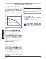
APPLIANCE DESCRIPTION
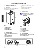
1.1 Overview
The model and serial number of the boiler
are printed on bottom right side.
Fig. 1.1
1
2
3
1
Case front panel
2
Control panel
3
Control panel cover
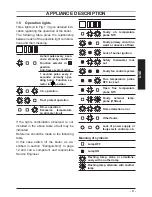
1.2 Control panel
4
C.h. circuit temperature and pressure
gauge
5
Lock-out signal lamp
6
Lockout reset button
7
Function selector and c.h. temp. control
knob
8
D.h.w. temperature control knob
9
Appliance operation lights
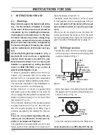
1.3 Isolation valves
Provide for the installation
of a stop valve on the D.c.w.
inlet pipe.
Fig. 1.2
13
11
10
12
10
C.h. return pipe
11
Gas inlet valve
12
Condensate drain pipe
13
C.h. flow pipe
1.4 Technical data
For detailed technical data see sections
"Technical Data" on page 18.
9
8
7
6 5
4
Fig. 1.3