


- 48 -
MAINTENANCE
MAINTENANCE
9.4 Combustion analysis check
If it is necessary to carry out a combustion
analysis remove the plugs indicated in Fig.
9.1.
Reference figures are given in the sections
"Technical Data" on pag. 18 of this manual.
If the analysis results are not within the ref-
erence figures in the
Service manual
, sec-
tion
Gas valve - Adjustment
.
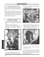
9.5 Cleaning the condensing heat
exchanger and burner
To remove the burner-fan group D (Fig. 9.5):
• Take off the front and side panels of the
case.
• Remove the sealed chamber lid.
• Disconnect the connectors of the ignition
electrodes E and detection electrode F
(Fig. 9.5).
Fig. 9.5
D
E
F
G
H
H
• Disconnect the rubber pipe I (Fig. 9.6).
• Unscrew the gas connector G (Fig. 9.5).
• Remove the fixing fork J and remove the
gas pipe K (Fig. 9.6).
Fig. 9.6
I
J
k
• Disconnect the connector of the fan L by
pressing the plastic hook M placed on the
rear side of the connector (Fig. 9.7).
Fig. 9.7
L
M
• Remove the nuts H (Fig. 9.5) and the
burner-fan group D.
If you notice dirt on the coil of the condens-
ing heat exchanger (16on page 16) brush
out it with a bristle paintbrush and remove
the dust with a hoover.