


- 31 -
INST
ALLA
TION
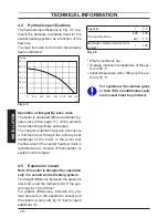
INSTALLATION
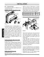
Fig. 6.7
90°=---1,65m
45°=---0,9m
Flue outlet pipe
“a”
Air intake pipe
“b”
Type C53
Type C43
N.B: The air intake and the flue outlet
must not terminate on opposite sides of
the building.
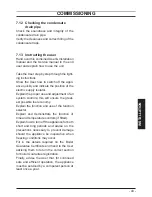
Vertical- roof kit (Fig. 6.8)
This kit allows vertical termination of the
flue pipe through the roof. The kit is 1.2 min
length. Extension pieces (Co-axial) are also
available which allows the flue system to be
extended to a total overall maximum per-
missible length of 10 m.
Optional 45° and 90° elbows can be used to
offset the flue route.
Each additional elbow reduces the overall
acceptable length of the flue system as fol-
lows:
For the elbow of 45° loss
0,5 m
For the elbow of 90° loss
1 m
Fig. 6.8
max = 10 m
90°=---1 m
45°=---0,5 m
ø 125
Type C33
Pluming kit (Fig. 6.9)
Co-axial ø 60/100 mm + vertical part ø 60
mm (flue outlet).
This kit allows the combustion air to be
sucked up and expel the burnt gases di-
rectly to the outside through a telescopic
co-axial flue (450-950 mm).
Fig. 6.9
90°=---1 m
45°=---0,5 m
90°=---0,85 m
45°=---0,65 m
ø 60 mm
ø 60/100 mm
Type C53