


- 29 -
INST
ALLA
TION
INSTALLATION
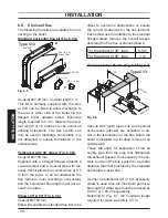
6.5 Joints
Functions
Pipe sizes
(o.d)
Gas, c.h. return, c.h. flow
ø 22
Pressure relief valve
ø 15
Condensate drain
ø 25 (plastic)
sizes in mm o.d.
6.6 Mounting the boiler
• Take the protective caps off the boiler
pipework.
• Thoroughly clean the connections.
• Mount the boiler on its bracket.
• Fix the gas cock I (¾”) to the boiler using
the ¾” gasket (Fig. 6.3)
• Fix the ø 22 mm pipe K to the cock I using
the ¾” gasket.
• Fix the ø 22 mm pipes J to the boiler using
the ¾” gaskets.
Fig. 6.3
I
J
J
k
• Connect the pipe L (Fig. 6.4) from the
pressure relief valve to the safety dis-
charge pipework.
• Fit the condensate drain 12 (Fig. 6.4) in
the air brake connected to the drainage
pipework. See also section "Condensate
drain" to page 23.
Fig. 6.4
L
12
6.7 Fitting the flue system
Refer to the assembly instructions con-
tained within the chosen flue kit packaging
for the correct assembly and installation.
In general, it has to be taken in considera-
tion that the horizontal sections of the flue
pipe must have an horizontal sloping not
less than 1.5 deg. (25 mm per metre) to-
wards the boiler.
In the standard horizontal flue kit (Fig. 6.6
A) the flue pipe is angled within the air duct
therefore the air duct must be horizontally
installed.
If one or more extensions have to be used
they must be adequately supported so that
there is no sag in the flue pipe and a mini-
mum fall of 1,5 deg. (25 mm per metre) over
the whole length towards the boiler is en-
sured.