


- 42 -
INST
ALLA
TION
COMMISSIONING
Fig. 7.12
Setting No.
Coeff. K
1
4
2
3
5
6
7
0
0,5
1
1,5
2
3
6
4
5
• To memorize the setting keep pressed the
reset button 6 for about 5 seconds until the
lights 9 briefly blinks simultaneously.
• To reset the boiler to the normal operation
turn it OFF and ON by the function selec-
tor knob 7. In any case, the boiler automat-
ically resets to its normal operation after
10 minutes.
After setting the coefficient K, position the
knob 7 as shown in Fig. 7.13 in order to ob-
tain the c.h. flow temperature accordingly
with the chart of Fig. 7.9.
Fig. 7.13
7
However, the setting point of the c.h. flow
temperature can be manually increased or
decreased within a range of ±15 °C by turn-
ing the knob 8.
The effect of the knob 7 for a coefficient K
set to 1,5 is illustrated in Fig. 7.14.
Fig. 7.14
20
30
40
50
60
70
80
External temperature °C
C.h. flow temperature °C
20
15
10
5
0
---5 ---10 ---15 ---20 ---25
K=1,5
+ 15 °C
--- 15 °C
7.10 Checking the ignition device
With the burner on high flame close the gas
cock.
After three ignition attempts (within about
three minutes), the lock-out signal lamp 5on
page 8 must appear.
To reset the boiler press and release the
boiler reset button 6on page 8.
7.11 Checking the flue system
The flue system should be visually checked
for soundness. Check all clamps, gaskets
and fixing are secure and tight.
Ensure that the flue terminal is sited cor-
rectly in accordance with the flue fitting in-
structions and Fig. 5.1 on page 22 of this
manual.
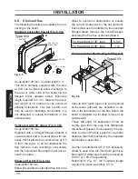
To carry out a combustion check refer to the
instructions given in the section "Combus-
tion analysis check" to page 47.
Reference figures are given in the "Techni-
cal Data" section page. 18 of this manual
(Flue gas figures).