


- 46 -
MAINTENANCE
GAS CONVERSION
Gas supply
Position of knob 8
Natural gas G20
1
L.P.G. G31
7
Fig. 8.9
• To change the setting turn the knob 8 on
a position corresponding to the gas used
as shown in Fig. 8.8. By turning the knob
8, the lock-out signal lamp 5 blinks quickly
(2 per seconds) indicating that the setting
has changed and must be memorised.
• To memorize the setting keep pressed the
reset button 6 for about 5 seconds until the
lamps 9 briefly blinks simultaneously.
Gas setting - second step
• Press the reset button 6 repeatedly (5
times) until the lamps 9 give the indication
as in Fig. 8.10 (gas type mode 2).
Where:
Lamp OFF
Lamp ON
Fig. 8.10
At this step it is possible to visualize the
current setting by keeping the reset button
6 pressed for more than 5 seconds. The
lamps 9 will flash a number of times corre-
sponding to the setting of the knob 8 in Fig.
8.8
• To change the setting turn the knob 8 on
a position corresponding to the gas used
as shown in Fig. 8.8. By turning the knob
8, the lock-out signal lamp 5 blinks quickly
(2 per seconds) indicating that the setting
has changed and must be memorised.
• To memorize the setting keep pressed the
reset button 6 for about 5 seconds until the
lamps 9 briefly blinks simultaneously.
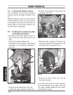
• Open the gas cock (11 in Fig. 8.11)
Fig. 8.11
11
Open
position
• To leave the gas setting mode and normal-
ly run the boiler turn it ON by the function
selector 7 (Fig. 8.12) on the desired opera-
tion and checking that the burner lights up
uniformly. In any case, the boiler automati-
cally resets to its normal operation after 10
minutes.
Fig. 8.12
9
8
7
6 5
• Calibrate the gas valve according to the
instructions given in the
Service manual
,
section
Gas valve - Adjustment.
• To adjust (if necessary) the maximun use-
ful central heating output required, see
section "Maximum output in c.h. mode" to
page 40.
• Stick on the inside of the left hand side pan-
el adjacent to the data badge the self-adhe-
sive label (included with the conversion kit)
indicating the type of gas, and the gas pres-
sures to which the appliance has been set.
Replace the adjustment protection cap.
• Replace the front panels of the case.