


- 20 -
INST
ALLA
TION
TECHNICAL INFORMATION
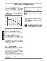
4.4 Hydraulic specifications
The hydraulic specifications in Fig. 4.3 rep-
resent the pressure (available head for the
central heating system) as a function of the
flow rate.
The load loss due to the boiler has already
been subtracted.
Fig. 4.3
0.0
0.1
0.2
0.3
0.4
0.5
0.6
0
200
400
600
800 1000 1200 1400
0
10
20
30
40
kPa bar
l/h
60
50
Operation of integral By-pass valve
The boiler is equipped with an automatic by-
pass valve (38on page 17), which protects
the condensing primary exchanger.
The integral automatic by-pass will ensure
a minimum flow through the primary heat
exchanger of the boiler in the event that
the flow around the central heating circuit is
restricted due to closure of thermostatic or
system control valves.
4.5 Expansion vessel
Note: this boiler is designed for operation
only in a sealed central heating system.
The height difference between the pressure
relief valve and the highest point in the sys-
tem may be 10m at most.
For greater differences, increase the pre-
load pressure in the expansion vessel and
the system, when cold, by 0.1 bar for each
additional 1m.
Fig. 4.4
Capacity
l
7,0
Pre-load pressure
kPa
100
bar
1,0
Maximum volume of water in the
system *
l
109
* Where conditions are:
• Average maximum temperature of the sys-
tem is 85 °C
• Initial temperature when filling up the sys-
tem is 10 °C
For systems with volumes great-
er than 109l, an additional expan-
sion vessel must be provided.