


- 36 -
INST
ALLA
TION
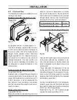
INSTALLATION
GY
WH
OR
GRYE
1
2
3
4
5
6
7
8
9 10
1
2
3
4
5
6
7
8
9 10
BU
C
1
2
Cylinder
thermostat
Room thermostat
A
B
MAINS
230V a.c.
Switched 3 Amp fused,
spur
L
N
Programmer
HTG
HW OFF
HW ON
L
N
Power supply
L
N
3 2 1
Do not
remove room
thermostat link
Room thermostat
A
B
4
5
Cylinder
thermostat
C
1
2
8
7
6
GY
WH
OR
GRYE
BU
2
3
8
5
7
MAINS
230V a.c.
Switched 3 Amp fused,
spur
L
N
2
3
1
Programmer
HTG
HW OFF
HW ON
L
N
2
1
4
6
7
Power supply
L
N
2
3
8
External control
terminal block
10 way
junction box
Mid---position
diverter valve
HTG = Heating
HW ON = Hot Water ON
HW OFF = Hot Water OFF
u
b
k
b
n
b
Valve colour key
WH --- White
GRYE --- Green/Yellow
GY --- Grey
OR --- Orange
BU --- Blue
BK --- Black
BN --- Brown
Fig. 6.20