


- 16 -
INST
ALLA
TION
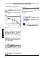
TECHNICAL INFORMATION
42
41
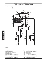
4.2 Main diagram
Fig. 4.2
10
C.h. return pipe
11
Gas inlet valve
12
Condensate drain pipe
13
C.h. flow pipe
14
Condensing heat exchanger
15
C.h. temperature probe NTC
16
Condensing heat exchanger
17
Safety thermostat
18
Flame-detecting electrode
19
Transformer
20
Air manifold
21
C.h. pressure relief valve
22
Automatic air purger valve
23
Main circuit drain valve
39
40
14
32
29
24
27
21
11
10
12
13
38
28
22
18
15
36
26
31
33
17
37
35
34
23
16