


- 39 -
INST
ALLA
TION
COMMISSIONING
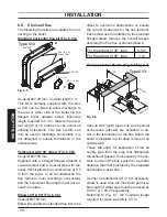
Fig. 7.4
An alternative, to avoid the removal of the
flue elbow, pour the water through the flue
sampling point (Fig. 7.5).
Fig. 7.5
Sampling points
Flue exhaust
7.6 Lighting the boiler
Some products incorporate an anti cycling
time delay. It is normal when first switch-
ing the boiler on for the boiler to operate
on heating for a few seconds then switch
off. After 3-4 minutes has elapsed the boiler
will then re ignite and operate perfectly nor-
mally.
If external controls are fitted (e.g. Time-
clock, room thermostat) ensure they ”call
for heat”.
• Turn on the electricity supply to the boil-
er, switching on the fused spur isolation
switch. The appliance operation light 9 will
flash every 4 seconds.
• Turn the function selector 7 as in Fig. 7.6.
The appliance operation light 9 will flash
every 2 seconds.
Fig. 7.6
9
7
6 5
The boiler will now go through an ignition
sequence and the burner will light.
If after four ignition attempts (about four
minutes) the boiler fails to light, the boiler
will go to lockout and the lock-out signal
lamp 5 will appear.
To reset the boiler press and release the
boiler reset button 6.
For the first lighting up and following main-
tenance procedures for the gas supply, it
may be necessary to repeat the resetting
operation several times so as to remove the
air present in the pipework.
After five consecutive resetting attempts the
reset button is inhibited. To restore its func-
tion it is necessary to switch the boiler off
and on from the electrical mains, using the
fused spur isolation switch fitted adjacent to
the appliance.
7.7 Checking the gas supply
pressure
This boiler has been factory tested to
the highest quality control standards
and set for the minimum and maximum
gas working pressures, connected to a
1m flue and a gas supply pressure of 20
mbar.