background image

KAYENNE K-FRAME  —  Installation & Service Manual

131

Lever Arm and Joystick Calibration


requirements (for example, to accommodate varying ambient room 
lighting levels).

1.

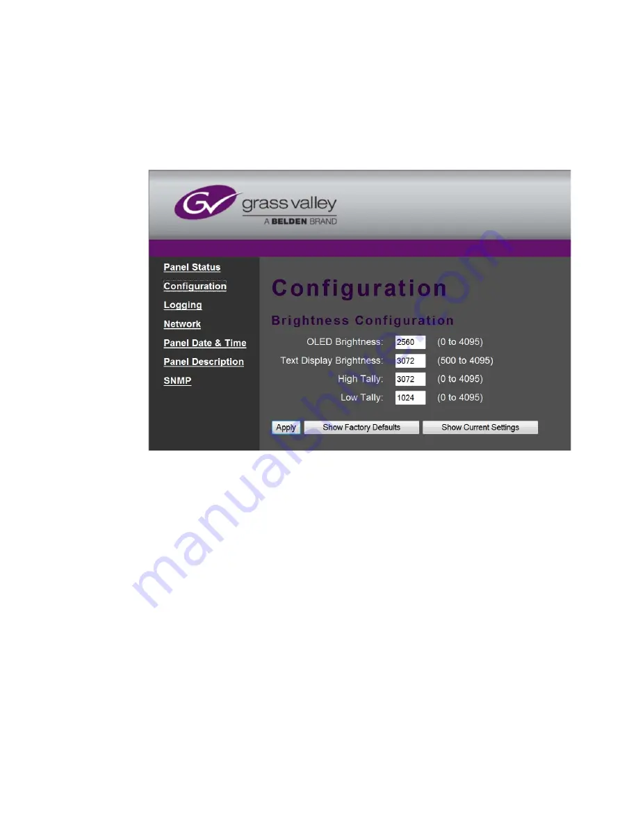
Access the Kayenne K-Frame Panel webpage, by entering its IP address 
in a web browser, then clicking on 

Configuration

.

Figure 88.  Control Panel Brightness Adjustment

2.

Enter the desired values for 

OLED

Text Display

High Tally

, and 

Low Tally

, and 

then click 

Apply

.

Note

To extend the life of display illumination hardware (in particular the OLEDs), 
the Control Panel automatically enters a panel saver state when its controls 
have not been touched for a specified time (ranging from 10 to 30 minutes). 
In the panel saver state all the Control Panel buttons and displays go dark, 
except the 

Key 1

 through 

Key 6

 and 

Key Prior

 buttons are illuminated blue 

and cycle. Touching any button or control on the Control Panel exits the panel 
saver state.

Lever Arm and Joystick Calibration

Kayenne K-Frame Lever Arms and Joysticks are calibrated at the factory 
and should not need to be adjusted when a new system is installed. Cali-
bration settings are stored within each module. 

Содержание Grass Valley Kayenne K-Frame

Страница 1: ...KAYENNE K FRAME VIDEO PRODUCTION CENTER Installation Service Manual Software Version 9 0 071887906 2015 09 15 ...

Страница 2: ......

Страница 3: ...KAYENNE K FRAME VIDEO PRODUCTION CENTER Installation Service Manual Software Version 9 0 071887906 2015 09 15 ...

Страница 4: ... brochures data sheets ordering guides planning guides manuals and release notes are available FAQ Database Solutions to problems and troubleshooting efforts can be found by searching our Frequently Asked Questions FAQ database Software Downloads Download software updates drivers and patches Grass Valley Technical Support For technical assistance contact our international support center at 1 800 5...

Страница 5: ...ck 19 Consignes de sécurité 23 Regulatory Notices Certifications and Compliances 27 FCC Emission Control 27 Canadian EMC Notice of Compliance 27 EN55022 Class A Warning 27 Canadian Certified Power Cords 28 Canadian Certified AC Adapter 28 FCC Emission Limits 28 Certification 28 Section 1 Introduction 31 Overview 31 Features 32 General 32 K Frame Standard Frame 33 K Frame Compact Frame 33 K Frame C...

Страница 6: ...trol Panel 60 1 ME 15 Control Panel 61 Separately Mounted Local Aux Stripe 35 25 Models 62 Control Panel Stripe PCU Connections 62 Touch Screen Menu Panel Installation 63 Menu Panel Dimensions 63 Menu Panel Connectors 63 Menu Panel Cooling 64 Menu Panel Articulated Arm Installation 64 Additional Kayenne Menu Panels 65 Touch Screen Menu Panel Using PCU 65 Touch Screen Menu Panel Using PC 65 Menu Ap...

Страница 7: ...94 MatchDef and SetDef Format Conversion 94 Reference Input 95 K Frame System Video Timing and Delay 95 Timing Analyzer 97 Time Zones and the Autotiming Window 98 ClipStore Cabling 99 Overview 99 ClipStore Video Cabling 99 Video Processor Frame GPI Relay Tally Interface 102 GPI and Relay Tally Connections 102 GPI Inputs 102 Relay Tally GPI Outputs 103 GPI In GPI Out Relay Tally Pin Assignments 105...

Страница 8: ...Control Panel Brightness Adjustment 130 Lever Arm and Joystick Calibration 131 Engineering Setups 132 Source Definition 132 Source Definition Inputs 132 Change Direct Source Definition 132 External Device Source Definition 133 Source Naming Background Information 133 Name Display Hierarchy 134 Fixed Sources 136 Source Patch Feature 136 Button Mapping 137 Output Assignments 137 Source Definition Ou...

Страница 9: ...tings 165 Source Definitions 166 Acquire Resources 168 Switcher Ethernet Camera Tally 170 Tally Calc Menus 170 Color Assign Menu 170 User Setups 172 Panel Prefs 172 Button Mapping Menu 172 Suite Prefs 174 Source Patch Menu 174 Default Keyframe 174 Configuration File Save and Load 174 Kayenne K Frame File Browser 174 File Storage Organization 176 Kayenne K Frame Drive Access 176 File Type Extension...

Страница 10: ...l Remote Aux Panels 199 Remote Aux Button Mapping 200 About the Status Menu 201 Acquire Resources 202 Acquire Multiviewer Resources with a Standard Frame 202 Acquire Multiviewer Resources with a Compact Six Keyer Frame 204 Acquire Multiviewer Resources with a Compact S series Four Keyer Frame 206 Section 6 External Interfaces 209 Introduction 209 General External Device Interfacing 210 Ports Devic...

Страница 11: ...rmanent Authorization Code 239 Temporary Authorizations 239 Control Panel Webpages 239 Control Panel NV Memory 240 Clear Control Panel NV Memory Procedure 240 Control Panel IP Information 241 Menu Panel IP Information 241 Video Processor Frame Maintenance 241 Video Processor Frame NV Memory 241 Clear NV RAM for Control Panel and Frame 241 Restore System Files 242 Restoring Multiple Suites 243 IP A...

Страница 12: ...ol Panel CF Card 259 Restore Control Panel Configuration Files 260 SNMP Monitoring 261 Introduction 261 Grass Valley Switcher Device Monitoring by SNMP 262 Video Processor Frame 263 Control Panel 263 Menu Panel Processor 263 SNMP Installation 263 SNMP Licensing 264 Licensing Definitions 264 SNMP Power Up License Processing 265 SNMP Licensed Configuration 265 Switcher Device SNMP Configuration Proc...

Страница 13: ...nowledge of the system The Kayenne K Frame Installation Service Manual contains information about installing configuring and maintaining the system The Kayenne K Frame Release Notes contain information about new features and system enhancements for a specific software version and also includes software installation procedures Always check the release notes for your current system software before y...

Страница 14: ...Frame Contact Grass Valley Product Management for more information on this SDK The KSP Graphical User Interface Instruction Manual provides information requirements and instructions for operating the 1 ME switcher Soft Panel GUI on a touch screen or regular PC including the optional customized keyboard The Switcher Concepts Manual provides an overview of switcher operation and describes basic swit...

Страница 15: ...ied to do so Safety Terms and Symbols Terms in This Manual Safety related statements may appear in this manual in the following form WARNING Warning statements identify conditions or practices that may result in per sonal injury or loss of life CAUTION Caution statements identify conditions or practices that may result in damage to equipment or other property or which may cause equipment crucial t...

Страница 16: ...nts or circuitry when power is present Indicates that dangerous high voltage is present within the equipment enclosure that may be of sufficient magnitude to constitute a risk of electric shock Indicates that user operator or service technician should refer to product manual s for important operating maintenance or service instructions This is a prompt to note fuse rating when replacing fuse s The...

Страница 17: ...using Disconnect mains power prior to servicing Use proper lift points Do not use door latches to lift or move equipment Avoid mechanical hazards Allow all rotating devices to come to a stop before servicing Cautions The following caution statements identify conditions or practices that can result in damage to equipment or other property Use correct power source Do not operate this product from a ...

Страница 18: ...trical codes Operation of this equipment at voltages exceeding 130 VAC requires power supply cords which comply with NEMA configurations International power cords if provided have the approval of the country of use Use correct replacement battery This product may contain batteries To reduce the risk of explosion check polarity and replace only with the same or equivalent type recommended by manufa...

Страница 19: ...prechende Qualifikationen für diese Arbeiten Sicherheit Begriffe und Symbole In diesem Handbuch verwendete Begriffe Sicherheitsrelevante Hinweise können in diesem Handbuch in der fol genden Form auftauchen WARNUNG Warnungen weisen auf Situationen oder Vorgehensweisen hin die Verletzungs oder Lebensgefahr bergen VORSICHT Vorsichtshinweise weisen auf Situationen oder Vorgehensweisen hin die zu Schäd...

Страница 20: ...hspannung im Gerätegehäuse hin die stark genug sein kann um eine Stromschlaggefahr darzustellen Weist darauf hin dass der Benutzer Bediener oder Service techniker wichtige Bedienungs Wartungs oder Servicean weisungen in den Produkthandbüchern lesen sollte Dies ist eine Aufforderung beim Wechsel von Sicherungen auf deren Nennwert zu achten Die im Text angegebene Sicherung muss durch eine Sicherung ...

Страница 21: ...kt nur in Umgebungen in denen keinerlei Explosionsgefahr besteht Hohe Kriechströme Das Gerät muss vor dem Einschalten unbedingt geerdet werden Doppelte Spannungsversorgung kann vorhanden sein Schließen Sie die beiden Anschlußkabel an getrennte Stromkreise an Vor Servicearbeiten sind beide Anschlußkabel vom Netz zu trennen Zweipolige neutrale Sicherung Schalten Sie den Netzstrom ab bevor Sie mit de...

Страница 22: ...Kompo nente von einem qualifizierten Servicetechniker untersuchen Kabel richtig verlegen Verlegen Sie Netzkabel und andere Kabel so dass Sie nicht beschädigt werden Stützen Sie schwere Kabelbündel ordnungs gemäß ab damit die Anschlüsse nicht beschädigt werden Richtige Netzkabel verwenden Wenn Netzkabel mitgeliefert wurden erfüllen diese alle nationalen elektrischen Normen Der Betrieb dieses Geräts...

Страница 23: ...dez à aucune intervention d entretien autre que celles contenues dans le manuel de l utilisateur à moins que vous ne soyez habilité pour le faire Consignes et symboles de sécurité Termes utilisés dans ce manuel Les consignes de sécurité présentées dans ce manuel peuvent apparaître sous les formes suivantes AVERTISSEMENT Les avertissements signalent des conditions ou des pratiques susceptibles d oc...

Страница 24: ...ent cette tension peut être suffisante pour constituer un risque de décharge électrique Signale que l utilisateur l opérateur ou le technicien de main tenance doit faire référence au x manuel s pour prendre con naissance des instructions d utilisation de maintenance ou d entretien Il s agit d une invite à prendre note du calibre du fusible lors du remplacement de ce dernier Le fusible auquel il es...

Страница 25: ... dans un environnement non explosible N utilisez pas ce produit dans un environnement dont l atmosphère est explosible Présence possible de courants de fuite Un raccordement à la masse est indis pensable avant la mise sous tension Deux alimentations peuvent être présentes dans l équipement Assurez vous que chaque cordon d alimentation est raccordé à des circuits de terre séparés Débranchez les deu...

Страница 26: ...n Acheminez les câbles correctement Acheminez les câbles d alimentation et les autres câbles de manière à ce qu ils ne risquent pas d être endommagés Supportez correctement les enroulements de câbles afin de ne pas endom mager les connecteurs Utilisez les cordons d alimentation adéquats Les cordons d alimentation de cet équipement s ils sont fournis satisfont aux exigences de toutes les régle ment...

Страница 27: ...ill be required to correct the interference at his own expense Changes or modifications not expressly approved by Grass Valley Group can affect emission compliance and could void the user s authority to operate this equipment Canadian EMC Notice of Compliance This digital apparatus does not exceed the Class A limits for radio noise emissions from digital apparatus set out in the Radio Interference...

Страница 28: ...s been evaluated for Electromagnetic Compatibility under the EN 55103 1 2 standards for Emissions and Immunity and meets the requirements for E4 environment This product complies with Class A In a domestic environment this product may cause radio interference in which case the user may be required to take adequate measures This product has been evaluated and meets the following Safety Certifica ti...

Страница 29: ...cker EN 55022 Class A Conducted Emissions Radiated Magnetic Field Emissions Peak Inrush Current EN55103 2 2009 Electromagnetic compatibility Product family standard for audio video audio visual and entertainment lighting control apparatus for professional use Part 2 Immunity Environment E4 EN 61000 4 3 Radiated RF Immunity EN 61000 4 2 Electrostatic Discharge ESD EN 61000 4 4 Electrical Fast Trans...

Страница 30: ...30 KAYENNE K FRAME Installation Service Manual Regulatory Notices ...

Страница 31: ...d post produc tion applications The K Frame Video Processor is the heart of the system providing exten sive video switching and signal processing capabilities This functionality is controlled using a Kayenne control surface a Karrera control surface the Soft Panel KSP option and or the Menu application running on a PC In addition a K Frame system supports direct control of external devices DDRs Se...

Страница 32: ...onfigurations of keyers from four M E outputs Aux bus transitions for dissolves and wipes on aux bus outputs Interfaces with Grass Valley routers and Kaleido Multiviewers and their control systems Optional Integrated Image Store capable of delivering up to 32 GB storage of Stills 3 000 images or Movies a total of 50 seconds of 1080p video LDK Series and LDX Series camera control with Ethernet tall...

Страница 33: ...ting 3D iDPMs 2D DPMs resizers on every keyer with 6 pairs per M E so iDPMs can be utilized for more complex effects The Controller M E has a complement of 6 full keyers with Chroma Key and 2D DPMs Up to 16 iDPMs Integrated Digital Picture Manipulators assigned as either floating iDPMs or within an eDPM at user s discretion K Frame Compact Frame Up to 80 inputs and 48 outputs Up to 5 M Es accessib...

Страница 34: ...y K Frame Video Processor The K Frame Video Processor is available in two sizes the 13RU Standard and the 6RU Compact The number of licensed boards present in the frame determines the number of MEs available as well as the number of video inputs outputs GPIOs and Relay Tallies Figure 1 K Frame Video Processors K Frame Control Surfaces Kayenne A Kayenne control surface typically consists of a Contr...

Страница 35: ...face Figure 5 Kayenne 1 ME 15 Control Surface 4 ME 35 Control Panel Menu Panel Menu Panel Articulated Arm 8623266_01 Panel Control Unit PCU Optional Device Control Module Optional Module Menu Panel Menu Panel Articulated Arm 8623266_02 Panel Control Unit PCU 3 ME 35 Control Panel Optional Device Control Module Menu Panel Menu Panel Articulated Arm 8623266_03 Panel Control Unit PCU 2 ME 25 Control ...

Страница 36: ...ct or disconnect the PCU to Control Panel cables while the system is powered on Flat or Curved Control Panel Orientation The main Kayenne Control Panel supports different physical orientations Besides a conventional flat surface a special support design permits a curved working surface where the MEs progressively tilt for improved ergonomics Figure 6 Curved and Flat Control Surface Installations F...

Страница 37: ...evices The Menu Panel has four USB ports two on the right side edge of the panel and two on the back for keyboard and mouse wired or wireless are sup ported Figure 8 Menu Panel with Articulated Arm Hold Hold Hold Hold A Hold Hold B U1 U2 Hold Hold Far Far Key Key Spl Split Rules Rules Hold Hold EMEM EMEM Sec Sec Aux Pri Key Key 3 Key Key 1 Macro Macro Key Key 5 Key Key 4 Key Key 2 Rtr Ke Key 6 EME...

Страница 38: ...o run on a PC platform The screen must be 1920x1080 resolution or better which is common in professional video environments A touchscreen is not required but can be very useful The KSP software is included with the switcher application software Pur chasing the option provides a software license that enables the interface for the selected switcher and includes a customized PC keyboard The license a...

Страница 39: ... 10 Kayenne Single Suite Compact Frame Example Multiple Suite Kayenne Panel System A K Frame system can be subdivided into two suites if desired each of which can have two control surfaces Surface A and Surface B Each surface has it s own set of Panel Preferences for configuration of the control panel behavior and independent macro systems to allow for independent building and running of macros by...

Страница 40: ...otocol for VTR control AMP advanced media protocol for Profile PVS Profile XP Media Plat form K2 M Series Turbo iDDR and T2 iDDR systems over Ethernet 8875_20 Suite 1 Menu on PC KSP 1 ME Soft Panel Option Keyboard Included Suite 2 4 ME 35 Kayenne Control Panel Menu Panel Panel Control Unit PCU Standard 13 RU K Frame Menu Panel Panel Control Unit PCU 2 ME 25 Kayenne Control Panel Customer Supplied ...

Страница 41: ... NXT Venus Triton and third party routers Jupiter and Encore router control systems Tally contact closure K Frame Ethernet Tally protocol Ethernet CPL to control Grass Valley external remote AUX Panels Grass Valley Editor protocol SNMP system monitoring Serial and Ethernet VDCP LDK Series LDX Series camera control with Ethernet tally via Connect Gateway ...

Страница 42: ...42 KAYENNE K FRAME Installation Service Manual Section 1 Introduction ...

Страница 43: ...located in the PCU The Stripes and Menu Panels are connected to the PCU via multi pin cables that carry power and communication signals Kayenne Control Panels ship to the customer as boxed Stripes which are assembled with the support structure on site You will need to know what Control Panel configuration s you intend to use at your facility in order to plan your installation effectively The Kayen...

Страница 44: ...o possible to create different Control Panel assemblies for example a 2 ME 35 since the parts are interchangeable Specific information for non standard configurations is not included in this document Control Panel Cooling The Kayenne Control Panel is externally powered and does not have internal cooling fans Electronics in the panel are convection cooled and require free air movement Do not instal...

Страница 45: ... 12 4 ME 35 Control Panel Dimensions Curved Installation Figure 13 4 ME Control Panel Cutout Dimensions Curved Installation 1533 7 mm 60 4 in 8623266_12 813 5 mm 32 0 in 1501 5 mm 59 1 in 622 8 mm 24 5 in 109 2 mm 4 3 in 14 3 mm 0 6 in 275 0 mm 10 8 in 10 3 mm 0 4 in 74 0 mm 2 9 in 625 1 mm 24 6 04 in 8623266_14 1311 5 1 mm 51 6 04 in 4 ME 25 Panel Cutout 4 ME Panel Curved Install Cutout 4 ME 35 P...

Страница 46: ...T A IL B A D E T A IL A 8557 2830 85 57 28 30 8557 2820 85 57 2820 855 7 2720 850 0 44 20 6x 862 0 3200 6x 850 0 442 0 4x 8557 2810 855 7 2860 862 0 3180 862 0 3180 850 0 7620 850 0 7620 862 0 3180 4x 850 0 6460 4x 8620 3180 4x 8500 6460 4x 86 20 3180 4x 8500 6460 4x 850 0 64 60 2x 850 0 6460 2x 8500 6460 2x 862 0 3180 2x 862 0 3180 2x 8557 2860 862 0 3180 8620 3180 850 0 7620 8500 7620 C D E T A ...

Страница 47: ... Control Panel Cutout Dimensions Flat Installation 1501 5 mm 59 1 in 622 8 mm 24 5 in 1533 7 mm 60 4 in 813 5 mm 32 0 in 771 5 mm 30 4 in 10 4 mm 0 4 in 14 1 mm 0 6 in 124 0 mm 4 9 in 10 3 mm 0 4 in 74 0 mm 2 9 in 720 0 mm 28 3 in 14 3 mm 0 6 in 8623266_17 8623266_16 4 ME Panel Flat Install Cutout 625 1 mm 24 6 04 in 4 ME 35 Panel Cutout 1503 5 1 mm 59 2 04 in 1311 5 1 mm 51 6 04 in 4 ME 25 Panel ...

Страница 48: ...90 862 0 3180 2x 85 00 6460 2x 8557 2790 8557 2790 855 7 28 90 862 0 3180 2x 85 00 64 60 2x 85 57 2890 8620 3180 2x 850 0 6460 2x A D E T A IL A 855 7 2720 8557 2830 855 7 2830 8557 2820 85 57 2820 8500 442 0 6x 862 0 32 00 6x 86 20 3200 2x 850 0 442 0 2x 862 0 3180 2x 86 20 3170 862 0 31 80 2x 850 0 6460 2x 8620 3170 862 0 31 70 862 0 3170 862 0 3170 8557 2710 B D E T A IL B 855 7 2710 855 7 2720...

Страница 49: ...h 25 source selection buttons are narrower in width but otherwise have the same dimensions as 35 source button models Figure 18 4 ME 25 Control Panel Dimensions 1341 7 mm 52 8 in 621 5 mm 24 5 in 4 ME 25 Flat Installation 1309 5 mm 51 6 in 124 0 mm 4 9 in 275 0 mm 10 8 in 4 ME 25 Curved Installation 8623266_32 ...

Страница 50: ...1533 7 mm 60 4 in 813 5 mm 32 0 in 1501 5 mm 59 1 in 622 8 mm 24 5 in 14 8 mm 0 6 in 14 3 mm 0 6 in 208 0 mm 8 2 in 10 3 mm 0 4 in 74 0 mm 2 9 in 720 0 mm 28 3 in 474 1 mm 18 7 in 13 9 mm 0 5 in 8623266_19_r1 3 ME Panel Curved Install Cutout 476 0 1 mm 18 7 04 in 491 0 1 mm 19 3 04 in 15 mm 60 in 32 0 2 0 mm 1 3 08 in 0 in 42 5 1 mm 1 7 04 3 ME 35 Panel Cutout 1503 5 1 mm 59 2 04 in 1311 5 1 mm 51...

Страница 51: ...820 855 7 2820 855 7 27 20 850 0 442 0 6x 8620 3200 6x 86 20 31 80 4x 85 00 6460 4x 862 0 3180 4x 86 20 31 80 4x 8500 6460 4x 850 0 6460 2x 8500 6460 2x 850 0 6460 2x 8620 3180 2x 862 0 3180 2x C D E T A IL C 8500 442 0 8620 3200 862 0 3200 86 20 31 80 86 20 3180 850 0 442 0 8620 3200 850 0 442 0 86 20 3180 2x 855 7 28 10 8557 2800 850 0 442 0 4x 862 0 3200 4x 86 22 54 20 4x 862 2 5410 4x 855 7 27...

Страница 52: ...mensions Flat Installation 1501 5 mm 59 1 in 474 1 mm 18 7 in 1533 7 mm 60 4 in 813 5 mm 32 0 in 622 8 mm 24 5 in 10 2 mm 0 4 in 13 9 mm 0 55 in 124 0 mm 4 9 in 10 3 mm 0 4 in 74 0 mm 2 9 in 720 0 mm 28 3 in 14 4 mm 0 6 in 8623266_55 8623266_56 3 ME Panel Flat Install Cutout 476 0 1 mm 18 7 04 in 3 ME 35 Panel Cutout 1503 5 1 mm 59 2 04 in 1311 5 1 mm 51 6 04 in 3 ME 25 Panel Cutout 720 mm 28 3 in...

Страница 53: ... 85 57 28 90 862 0 3180 2x 85 00 6460 2x 8557 2780 85 57 2780 855 7 2890 8620 3180 2x 850 0 64 60 2x 85 57 28 90 86 20 3180 2x 850 0 6460 2x A D E T A IL A 8557 2720 8557 2830 855 7 2830 855 7 2820 855 7 2820 850 0 442 0 6x 862 0 3200 6x 862 0 32 00 2x 8620 3180 2x 850 0 6460 2x 8620 3170 8620 3170 862 0 3170 86 20 3170 85 57 2710 B D E T A IL B 855 7 2710 855 7 2720 85 57 27 10 85 57 28 30 855 7 ...

Страница 54: ...anels with 25 source selection buttons are narrower in width but otherwise have the same dimensions as 35 source button models Figure 25 4 ME 25 Control Panel Dimensions 1341 7 mm 52 8 in 621 5 mm 24 5 in 3 ME 25 Flat Installation 1309 5 mm 51 6 in 124 0 mm 4 9 in 208 0 mm 8 2 in 3 ME 25 Curved Installation 8623266_33 ...

Страница 55: ... Installation 8623266_24 1533 7 mm 60 4 in 813 5 mm 32 0 in 1501 5 mm 59 1 in 474 1 mm 18 7in 14 3 mm 0 6 in 158 0 mm 6 2 in 10 3 mm 0 4 in 74 0 mm 2 9 in 8623266_25_r1 2 ME Panel Curved Install Cutout 330 5 1 mm 13 0 04 in 340 5 1 mm 13 4 04 in 32 0 2 0 mm 1 3 08 in 0 in 42 5 1 mm 1 7 04 2 ME 35 Panel Cutout 1503 5 1 mm 59 2 04 in 1311 5 1 mm 51 6 04 in 2 ME 25 Panel Cutout 720 mm 28 3 in 476 0 1...

Страница 56: ... 8x 862 0 3200 8x 85 57 28 00 8557 2810 85 57 2890 855 7 2850 86 20 3180 4x 850 0 6460 4x 85 00 6460 2x 86 20 3180 2x 855 7 2770 86 20 32 00 2x 850 0 442 0 2x 862 0 3180 2x 8557 2700 855 7 2830 8557 2830 855 7 2820 855 7 2820 8557 2720 850 0 442 0 6x 862 0 3200 6x 8620 3180 850 0 76 20 85 57 2860 8500 7620 8620 3180 85 57 2700 85 57 27 80 855 7 2710 855 7 27 10 8557 2720 86 20 31 70 862 0 3170 85 ...

Страница 57: ...E Control Panel Cutout Dimensions Flat Installation 8623266_58 1533 6 mm 60 4 in 813 5 mm 32 0 in 1501 5 mm 59 1 in 474 1 mm 18 7in 14 3 mm 0 6 in 124 0 mm 4 9 in 10 3 mm 0 4 in 74 0 mm 2 9 in 10 mm 0 4 in 8623266_59_r1 2 ME Panel Flat Install Cutout 327 5 1 mm 12 9 04 in 2 ME 35 Panel Cutout 1503 5 1 mm 59 2 04 in 1311 5 1 mm 51 6 04 in 2 ME 25 Panel Cutout 720 mm 28 3 in 476 5 1 mm 18 8 04 in ...

Страница 58: ...0 8557 2850 8557 2770 8557 2850 8620 3180 2x 8500 6460 2x 855 7 2890 8620 3180 2x 8500 6460 2x A DE TAIL A 8557 2720 8557 2830 8557 2820 8557 2820 8500 4420 6x 8620 3200 6x 8620 3200 2x 8620 3180 2x 8500 6460 2x 8620 3170 8620 3170 8620 3170 8557 2710 B DE TAIL B 8557 2710 855 7 2720 855 7 2710 855 7 2830 8557 2830 8557 2820 8557 2820 8620 3200 6x 8500 442 0 6x 850 0 6460 2x 862 0 3180 2x 850 0 64...

Страница 59: ... in 325 4 mm 12 8 in 10 3 mm 0 4 in 74 0 mm 2 9 in 15 2 mm 0 60 in 15 8 mm 0 62 in 327 5 1 mm 12 9 04 in 8623266_22 1311 5 1 mm 51 6 04 in 2 ME 25 Panel Cutout 2 ME Panel Flat Install Cutout Local Aux Installed Separately 2 ME 35 Panel Cutout 1503 5 1 mm 59 2 04 in 8557 2850 862 2 5420 2x 8622 5410 2x 8557 2850 8557 2760 8620 3180 2x 8620 3180 2x 8500 6460 2x 8500 6460 2x 7 2850 8557 2850 8557 276...

Страница 60: ...anels with 25 source selection buttons are narrower in width but otherwise have the same dimensions as 35 source button models Figure 35 2 ME 25 Control Panel Dimensions 1341 7 mm 52 8 in 621 5 mm 24 5 in 2 ME 25 Flat Installation 1309 5 mm 51 6 in 124 0 mm 4 9 in 158 0 mm 6 2 in 2 ME 25 Curved Installation 8623266_34 ...

Страница 61: ... 9 in 325 4 mm 12 8 in 10 3 mm 0 4 in 74 0 mm 2 9 in 15 2 mm 0 60 in 15 8 mm 0 62 in 327 5 1 mm 12 9 04 in 8623266_28 728 1 mm 28 7 04 in 1 ME 15 Panel Cutout 850 0 4960 6x 850 0 4420 6x 855 7 1480 855 7 1480 855 7 1480 855 7 3180 855 7 3180 850 06460 4x 850 06460 2x 850 06460 2x 862 0 3180 4x 862 0 3180 2x 862 0 3180 2x 8557 2850 855 7 2850 855 7 2850 2x 855 7 2760 8557 2760 855 7 3190 855 7 3190...

Страница 62: ... 6 2 04 in 591 5 1 mm 23 3 04 in Local Aux 25 Panel Cutout Aux Panel Installed Separately Local Aux 35 Panel Cutout 783 5 1 mm 30 8 04 in 8623266_30 781 5 mm 30 8 in Local Aux 35 Width 813 7 mm 32 0 in 589 5 mm 23 2 in Local Aux 25 Width 621 7 mm 24 5 in 154 7 mm 6 1 in 15 2 mm 0 60 in 15 8 mm 0 62 in 10 3 mm 0 4 in 74 0 mm 2 9 in 850 0 4960 4x 850 0 4420 4x 855 7 1480 855 7 1480 855 7 1480 855 7 ...

Страница 63: ...s both power and communications signals CAUTION Do not connect or disconnect the multi pin cables linking a Kayenne Menu Panel to the PCU while the PCU is powered up Damage to the equipment can result Front View Rear View Side View Right 8623266_07 Bottom View 170 9 mm 6 73 in 245 9 mm 9 68 in 171 9 mm 6 77 in 19 1 mm 79 in 76 2 mm 3 00 in 417 8 mm 16 45 in 270 0 mm 10 63 in 64 1 mm 2 52 in 129 4 ...

Страница 64: ...the Menu Panel chassis Mounting the panel free standing with the articulated arm allows maximum air movement and is the preferred installation method If an alternative method is used ensure that all vents are unobstructed and adequate airflow is available Menu Panel Articulated Arm Installation The Kayenne Menu Panel has VESA 75 threads on the back that can be used to mount the Menu Panel to the s...

Страница 65: ... Panel processor board in the PCU A multi pin cable is pro vided with the option to supply power and signals to the Menu Panel Touch Screen Menu Panel Using PC A Touch Screen Menu Panel can be configured to operate without a PCU using a PC Communication between the Menu Panel and the K Frame system is handled using the PC s Ethernet connection A special power supply brick is required which powers ...

Страница 66: ...ayenne menu application can also be run on a standard PC permit ting mouse and keyboard control from a nearby laptop or remote control of the K Frame system from any location on the network If a PC is used for Kayenne Menu operation the PC s IP address must be set to a compatible value to work with the rest of the K Frame system ...

Страница 67: ...his unit Make sure you install the frame to allow for cooling airflow When the unit is installed in a rack ventilation openings should not be blocked or other wise covered Air intake holes exist on the right side of the K Frame Video Processor as you face the frame front and air exhaust holes are on the left Power Connections When connecting the unit to the supply circuit be sure that the supply c...

Страница 68: ... K Frame 13 RU Dimensions Front View Note Mounting a K Frame in a rack immediately below equipment that extends forward from the rack may not provide enough clearance to completely remove the K Frame door See 13 RU Video Processor on page 68 482 mm 19 0 in 8875_02 439 mm 17 3 in 460 mm 18 1 in 577 mm 22 7 in ...

Страница 69: ...KAYENNE K FRAME Installation Service Manual 69 13 RU Video Processor Figure 45 K Frame 13 RU Dimensions Top View 442 mm 17 4 in 8875_05 37 mm 1 5 in 566 mm 22 3 In 602 mm 23 7 in 483 mm 19 0 in ...

Страница 70: ...tallation Figure 46 K Frame 13 RU Rack Mounting and Cooling Airflow CAUTION K Frame installations require the use of the provided rear rack supports Air Intake Chassis Bottom Air Intake Chassis Bottom Rear Rack Support Rear Rack Support Air Exhaust Chassis Top 8875_14 ...

Страница 71: ...ust remain in place and closed during normal system operation to maintain maximum cooling efficiency F1 ME A1 A2 F2 ME B1 B2 F4 ME C1 C2 F5 ME D1 D2 F6 IMAGE STORE F3 CONTROLLER ME F11 F13 F15 F17 F12 F14 F16 F18 ON OFF Fan Assembly 8875_03 ME C1 C2 ME B1 B2 ME A1 A2 Image Store ME D1 D2 Controller with ME Front Slots F6 F1 Slots F18 F11 Reserved for future use ...

Страница 72: ... 20 19 18 17 16 15 14 13 12 11 10 9 8 7 6 5 4 3 2 1 TALLY GPI INPUTS 32 31 30 29 28 27 26 25 24 23 22 21 20 19 18 17 16 15 14 13 12 11 10 9 8 7 6 5 4 3 2 1 TALLY GPI INPUTS 32 31 30 29 28 27 26 25 24 23 22 21 20 19 18 17 16 15 14 13 12 11 10 9 8 7 6 5 4 3 2 1 OUTPUTS 16 15 14 13 12 11 10 9 8 7 6 5 4 3 2 1 OUTPUTS 16 15 14 13 12 11 10 9 8 7 6 5 4 3 2 1 INPUT OUTPUT 4 3 2 1 4 3 2 1 INPUT OUTPUT 4 3 ...

Страница 73: ...Frame 6 RU Dimensions Front View Note Mounting a K Frame in a rack immediately below equipment that extends forward from the rack may not provide enough clearance to completely remove the K Frame door See 13 RU Video Processor on page 68 482 mm 19 0 in 8875_06 439 mm 17 3 in 460 mm 18 1 in 264 mm 10 4 in ...

Страница 74: ...74 KAYENNE K FRAME Installation Service Manual Section 3 Frames Installation Figure 50 K Frame 6 RU Dimensions Top View 442 mm 17 4 in 8875_09 596 mm 22 0 In 559 mm 23 5 in 483 mm 19 0 in 37 mm 1 5 in ...

Страница 75: ...Cooling Airflow CAUTION K Frame installations require the use of the provided rear rack supports 6RU Compact S series Front Views with Doors Removed The Compact S series Frame includes four keyers per ME and two Multiv iewers on the Controller board Air Intake Rear Rack Support Air Exhaust 8875_13 Rear Rack Support ...

Страница 76: ... per ME Figure 53 K Frame Compact Performance Frame 6 RU Front View with Door Removed CAUTION The Video Processor front door must remain in place and closed during normal system operation to maintain maximum cooling efficiency F3 ME B F4 IMAGE STORE F2 CONTROLLER F1 ME A ON OFF 8875_23 Front Slots F1 F4 Fan Assembly ME A Controller ME B F3 ME B F4 IMAGE STORE F2 CONTROLLER F1 ME A ON OFF 8875_07r1...

Страница 77: ...ule 4 Module 1 Modular I O Up to 4 modules Control I O Reference Ethernet and Serial ports Input Video 32 inputs 8 GPI in out and 24 Tally Up to 2 modules Power Supply AC ON OFF Boot Mode DIP Switch Power Switch 8875_10 LEDs 15 Test Points with LEDs 9 and Text Display Reset Button RS 232 PS2 Keyboard VGA USB two ports usable with door closed USB two ports NOTE Ports and indicators here are intende...

Страница 78: ... Rear Views LINK ACTIVITY OFF 10 AMBER 100 GREEN 1000 LAN ANALOG REFERENCE DIAGNOSTIC MODE 8 7 6 5 4 3 2 2 4 6 1 3 5 1 SERIAL PORTS RS422 485 8875_18r1 Illuminated LED indicates Port 1 is in diagnostic mode Reference Serial Ports 8 RS422 486 Ethernet 6 communications 482 mm 19 0 in Front View Cover Removed Front View with Cover Rear View 8875_11 44 mm 1 72 in 45 mm 1 8 in 79 mm 3 1 in 217 mm 8 5 i...

Страница 79: ...upply Frame Rack Placement The K Frame power supply frame is ideally rack mounted immediately above the Standard Video Processor chassis The power supply frame is then supported by the lower chassis and eliminates the need for power supply rear rack supports 8875_15 466 mm 18 3 in 442 mm 17 4 in 448 mm 17 6 in 265 mm 10 4 in 483 mm 19 0 in 490 mm 19 2 in 41 mm 1 6 in 449 mm 17 7 in ...

Страница 80: ...Frame see 13 RU Video Processor on page 68 If the power supply frame is not mounted above the K Frame chassis rear rack supports are required If mounting in an alternative location allow for the 34 DC interconnect cable length Figure 60 Isolated K Frame Standard Power Supply Rack Installation Air Exhaust K Frame Chassis Power Supply Frame 8875_21 Air Intake Air Intake Rear Rack Support Air Exhaust...

Страница 81: ...have a module installed Each cell has its own AC line cord The supplies are power factor corrected and automatically accommodate low line 120V nominal or high line 240V nominal The power supply frame has a rating of 100 240 volts although it is designed and tested for a range of 90 to 264 volts to accom modate under and over voltage conditions A Compact K Frame is sup plied with one power module A...

Страница 82: ...th all options installed and running at 120 volts will draw a total of approximately 12 amps from the line cords At 100 volts this increases to approximately 14 amps This load will be evenly distributed among the line cords However if one or more power supplies go offline it is possible for the entire 12 14 amps to be drawn by one line cord For this reason it is recommended that each line cord be ...

Страница 83: ...ree char acteristics of the switcher should be kept in mind when provisioning AC power for the system which will result in the most reliable system possible Consider brown out Modern switching power supplies are constant power devices and as such unlike resistive loads the input current increases as the input voltage decreases Consider power supply failure If two or three power modules are present...

Страница 84: ...Most of the above is not an issue if high line 240V operation is used Since AC line currents are approximately half of those at low line exceeding the current rating of a circuit should not be a problem In areas where there is a choice between high line or low line operation the user should consider the advantages and disadvantages of each power sourcing scheme Replacing Compact Power Supplies Com...

Страница 85: ...hat it latches in the closed position K Frame Video Processor Door Removal Clearance CAUTION The Video Processor front door must remain in place and closed during normal system operation to maintain maximum cooling efficiency The K Frame Video Processor door on all K Frames can be completely removed when installed in a rack immediately below conventional flush mounted rack ear only equipment If th...

Страница 86: ...under another K Frame chassis may not provide enough clearance to remove the K Frame door If mounted below equipment that extends forward from the rack allow at least 24 mm 0 94 in of vertical clearance above the K Frame to permit door removal A flush design 1 RU blank filler panel can be used for clear ance if required ...

Страница 87: ... 8877_02 Technical Director s Laptop CD ROM Drive Disable Internet or Wireless Connections Isolate K Frame System from External Network Ethernet Serial Control Custom Multi Pin Menu 15m 50ft max length Custom Multi Pin Panel 15m 50ft max length Maintenance Only board front edge Panel Main LAN Panel Aux LAN not used Ehternet Switch 1 2 3 4 5 6 7 8 Kayenne PCU Menu CPU Hard Disk Menu CPU option Hard...

Страница 88: ...ion to devices connected to that K Frame s or PCU s internal Ethernet switches Only connect devices that are K Frame system related The use of two Ethernet cables to connect the PCU to the K Frame Video Processor is recommended Figure 64 PCU to K Frame Network Connection Methods The PCU Ethernet switch to K Frame Video Processor Ethernet switch cable connection is used for Menu Panel communication...

Страница 89: ...multi suite K Frame system Figure 65 Two Suites with Two Control Surfaces Using One PCU 8877_04 Panel Main LAN Ehternet Switch 1 2 3 4 5 6 7 8 Kayenne PCU Menu CPU Hard Disk Menu CPU option Hard Disk Panel CPU Compact Flash Menu Panel Kayenne Control Panel Local Aux Stripe ME Stripe ME Stripe ME Stripe Menu Panel Kayenne Control Panel ME Stripe ME Stripe Kayenne Satellite Panel Satellite Stripe Su...

Страница 90: ... Kayenne network and keeps it isolated Any Ethernet switches added specifically for use with the 8877_05 Menu Panel Kayenne Control Panel Local Aux Stripe ME Stripe ME Stripe ME Stripe Suite Boundary Ethernet Custom Multi Pin Menu 15m 50ft max length Custom Multi Pin Panel 15m 50ft max length Ethernet 100m 300ft max single hop length unlimited distance using switches Panel Main LAN Ehternet Switch...

Страница 91: ... 45 male connector at each end of cable Length 100BaseT 1000BaseT 328 ft 100 m maximum 10BaseT 984 ft 300 m maximum Use additional switches to exceed maximum cable runs Switch Speed 10 100 1000 Mbps Ports RJ 45 auto negotiating 10 100 1000 Mbps number of ports required is dependent upon system size Frame and PCU ports are capable of 1000 Mbps Using a 1000 Mbps Ethernet switch enhances Image Store ...

Страница 92: ...es Device IP Address Video Processor Frame CPU 192 168 0 170 Image Store CPU 192 168 0 171 Control Panel Surface 1A 192 168 0 173 Touch Screen Menu Panel 1 192 168 0 175 Touch Screen Menu Panel 2 192 168 0 176 Control Panel Surface 1B 192 168 0 177 Control Panel Surface 2A 192 168 0 178 Control Panel Surface 2B 192 168 0 179 Clip Store 192 168 0 180 32 Crosspoint Remote Aux Panels V1 6 5 and highe...

Страница 93: ... particular Stripe for example Device Control or Master E MEM modules can use any available PCU connector Modules to be associated with a particular Stripe like a Transition Module must be connected to the next higher PCU port for that Stripe For example if you wish to use a Transition Module with ME 4 that uses PCU Port 4 plug the Satellite Panel into PCU Port 5 and move the Local Aux Stripe conn...

Страница 94: ...or Menu Panels are assigned to suites during system configuration MatchDef and SetDef Format Conversion K Frame Video Processor modular I O is available for MatchDef and SetDef signal conversion or to increase the number of standard video inputs and outputs This functionality is configurable in software The 13 RU Standard K Frame can hold up to eight modules and the 6 RU can hold up to four Each m...

Страница 95: ...must be within this range to be properly timed at the output The calculation of the actual video delay of a specific input is the Nominal Switcher Delay minus the input time location within the auto timing window the time location value can be zero positive or negative A timing diagram of the input autotiming window and various switcher delay values is provided Table 5 K Frame System Timing 4 5 ME...

Страница 96: ...s that reach the switcher at the earliest point in the autotiming window B μs will have a total delay equal to the Nominal Switcher Delay A μs plus the autotiming window range This value is the Maximum Switcher Delay value D μs On K Frame systems the autotiming window varies depending on the operating mode The Timing Analyzer in the Video Settings Menu displays this autotiming information Note The...

Страница 97: ...pper right Analyzer Source soft knob and data pad The relative position of that source is reported in lines and μs Positive values indicate the source is later in time than the internal sync generator and negative values indicate the source is earlier Kayenne K Frame systems have an autotiming window Sources that fall within that window will be properly timed throughout the Kayenne K Frame system ...

Страница 98: ...ource fed to the switcher must be within the autotiming range of all six time zones If not the source will be in time on some MEs but not on others As illustrated in the figure a source centered in one time zone s autotiming range can be too early or late for other switcher time zones If a signal falls just outside the autotiming window that image will be shifted one line up or down On SD systems ...

Страница 99: ...ded in the packaging ClipStore Video Cabling The ClipStore channels on the server backplane are labeled C1 C4 Channel 1 through Channel 4 on the Summit from left to right The Solo backplane is not labeled Channel 1 is on the left and Channel 2 is on the right when facing the backplane ClipStore requires SDI connections for both video and key two connec tions In Out per channel for recording and pl...

Страница 100: ...Amplifiers can be used to distribute Kayenne K Frame Aux Bus output The example in Figure 72 shows DAs being used for both the Video and Key Aux Bus outputs from the frame Channel 2 Channel 3 Channel 4 Channel 1 Kayenne Video Processing Frame C1 SDI IN 2 C1 SDI IN 1 C1 SDI OUT 2 C1 SDI OUT 1 C2 SDI IN 2 C2 SDI IN 1 C2 SDI OUT 2 C2 SDI OUT 1 C3 SDI IN 2 C3 SDI IN 1 C3 SDI OUT 2 C3 SDI OUT 1 C4 SDI ...

Страница 101: ...ing Figure 72 ClipStore Connection Using Distribution Amplifiers Channel 2 Channel 3 Channel 4 Channel 1 Kayenne Video Processing Frame Aux Bus Out Key to DA even Aux Bus Out Video to DA odd ClipStore Summit 8623266_96 Aux Bus Pair Out DA DA Video Key Channels In ...

Страница 102: ...ally is driven by the Relay Tally system software Relay tally connections can be used to trigger GPIs on external devices GPI Inputs The purpose of the GPI In pins is to provide a stimulus from the external devices to the switcher A simple connection of two pins activates the cor responding input An external relay contact or an open collector output can be employed CAUTION When connecting to an op...

Страница 103: ...mon or isolated bus scheme can extend across multiple connectors For example a situation may require two isolated common buses half of the commons form the first common bus and the other half form the second common bus The example shown in Figure 74 illustrates two common configurations The first four outputs have the common bus tied to ground This drives a logic system The last outputs have the c...

Страница 104: ...idirectional either polarity voltage can be applied If the switcher GPI Relay Tally outputs are used to drive downstream DC relays be sure to install diodes across the relay coils to clamp inductive spikes Shielded cable is recom 50 pin Connector Pin Numbers Tally1A Tally2A Tally3A Tally4A Tally5B Tally6B GPIOut3G GPIOut4G GPIOut5H GPIOut6H GPIOut7H GPIOut8H Video Processor Frame User Equipment Co...

Страница 105: ...able 6 Relay Tally and GPI Output Specifications Maximum current for any one output 1 amp AC DC Maximum current for any one common 2 amp AC DC Maximum off open circuit voltage between output and common 60 Volts peak Maximum voltage between any point and ground chassis 60 Volts peak Table 7 Input Module Connectors Module Number Signals 8RU Frame 13 RU Frame 1 GPI In 1 8 Yes Yes GPI Out 1 8 Relay Ta...

Страница 106: ...U Tally83AC Tally107AJ 25 9 Tally12C Tally36L Tally60U Tally84AC Tally108AJ 26 42 TallyComD TallyComM TallyComV TallyComAD TallyComAK 27 26 Tally13D Tally37M Tally61V Tally85AD Tally109AK 28 10 Tally14D Tally38M Tally62V Tally86AD Tally110AK 29 43 Tally15D Tally39M Tally63V Tally87AD Tally111AK 30 27 Tally16D Tally40M Tally64V Tally88AD Tally112AK 31 11 TallyComE TallyComN TallyComW TallyComAE Tal...

Страница 107: ...ments RS 232 serial ports are located on each processor board Video Processor Panel Processor Menu PC available for maintenance and diagnostics Standard VGA and keyboard ports present on all processor boards are also available for maintenance Table 9 RS 422 485 Pinouts Socket Pin Bus Controller Tributary 1 Chassis Ground Chassis Ground 2 RxA TxA 3 TxB RxB 4 Signal Ground Signal Ground 5 Not used N...

Страница 108: ...108 KAYENNE K FRAME Installation Service Manual Section 4 System Cabling ...

Страница 109: ...2 Set IP addresses for your facility if not using defaults Node Settings will also need to be configured for proper system communications see page 117 3 If necessary adjust Control Panel button and display illumination page 130 4 If necessary calibrate Control Panel lever arms and joystick see Maintenance section 5 Define your basic Engineering Setups Essential settings include Source Definition s...

Страница 110: ... can affect both suites if a second suite has been configured Engineering Setups are intended to be used and main tained by technical staff These parameters are typically set once and seldom changed unless the facility changes in some way new devices installed signals rerouted etc User Setups User Setups can customize Kayenne K Frame system behavior for personal preferences and to meet workflow re...

Страница 111: ...ration file along with other Remote Aux Panel settings GV Switcher Menu Application Note A brief description of the GV Switcher menu application is presented here Refer to the separate Kayenne K Frame User Manual for detailed information The GV Switcher menu application is used to configure your Kayenne K Frame system This application can run on a user supplied PC using a mouse and keyboard and ca...

Страница 112: ...s Data pads are active areas on the screen that display a summary of the status of an object and when clicked or touched bring up additional con trols and information for that object Touch buttons are labeled by their function and do not display data Clicking or touching these buttons will immediately activate their function Touch buttons can control on off functions and have an indicator on the l...

Страница 113: ...touch buttons are directly above the Menu touch buttons Touching one of these buttons displays that category see Figure 75 on page 112 As each menu is accessed a button for it appears in the scrolling History pane on the left providing a quick return to that menu Favorites can also be programmed for quick access to specific menus that are not overwritten Note The optional eDPM system has its own s...

Страница 114: ...of the screen Default Kayenne K Frame System Communications Kayenne K Frame systems ship with factory default settings that allow components to communicate with one another when powered up pro vided they are connected properly These Kayenne K Frame components appear on the Status menu We recommend you use an isolated Ethernet network with your Kayenne K Frame system to prevent possible IP address ...

Страница 115: ... Pro cessor Frame either directly or though an Ethernet switch The IP Address the menu application will use to communicate with the Frame must be in the Frame IP Address field of the Eng Setup Frame Suite Nodes ID menu to identify which Frame the Menu Panel will connect to The Menu Panel s IP address must be in the IP Address field of the Control Surfaces menu to register that Menu Panel as a node...

Страница 116: ... Eng Setup Node Settings Frame Suite Nodes ID Figure 77 Frame Suite Nodes ID Menu 2 Enter the IP address the menu will use to communicate with the Frame in the Frame IP Address field 3 A Restart menu dialog box will appear Figure 78 Restart Menu Dialog Box 4 You can either touch Restart Now to restart Menu Panel application or you can Cancel make changes to the Image Store IP Address and Track DPO...

Страница 117: ...the Internet IP Address Background Information Each device connected to any Ethernet network must have a unique IP address An IP address has two components the network address and the node address The Subnet mask defines the dividing line between the two The first three octets of Subnet mask provide the network address the fourth is the node address Nodes with the same network address can com muni...

Страница 118: ...able communication between Kayenne K Frame and other facility devices you will need to change the Kayenne K Frame system default network addresses to match the facility address or place a router between Kayenne K Frame and the facility networks This complexity of network configuration is beyond the scope of this manual Consult a networking expert if such networking is desired See your network Syst...

Страница 119: ...network Figure 80 Figure 80 K Frame Switcher Installer Program Hierarchy Multiple Systems The default name for every Kayenne K Frame Video Processor is SystemA and this works well when only one system is present on the network How ever if more than one Kayenne K Frame system with the default name is present all the Frames and Control Panels will be grouped under that name If you have more than one...

Страница 120: ... K Frame system components and is physically connected to the Kayenne K Frame network 2 Double click on the K Frame Installer icon The K Frame Switcher Installer program will be launched Note The K Frame Switcher Installer program cannot run if the separate NetConfig application or any monitoring program is also being run simultaneously on that same Menu Panel or PC 3 Click on the System button on...

Страница 121: ...ring new IP Node addresses may also be necessary Other K Frame Switcher Installer Program Functions The K Frame Switcher Installer program can also be used to install the KSP and NetConfig applications on that PC using the buttons on the left In addition the K Frame Switcher Installer application has the following other features accessed by clicking on its labeled button Rescan Re scans the networ...

Страница 122: ...ss of the Kayenne K Frame Video Processor or Control Panel before you can change it using a Web browser mouse and keyboard Note The NetConfig application included with the Kayenne K Frame software can be used to find IP addresses of devices accessible on the network Refer to the separate NetConfig Instruction Manual for more information 1 Using any web browser connected to your Kayenne K Frame net...

Страница 123: ... using the Video Processor Frame web page See Set the IPs Using Device Web Pages on page 122 for more information Changing Control Panel IP Addresses A Kayenne K Frame Control Panel s IP address can be changed using various methods K Frame Switcher Installer program see Setting IPs with the K Frame Switcher Installer Program on page 118 the Kayenne K Frame Control Panel webpage see Set the IPs Usi...

Страница 124: ...them to the network This will require a mouse and keyboard connected to a PC disconnected from the network Check with your network administrator to learn what IP addresses should be used at your facility Setting the IP Address A PC equipped with an Ethernet interface and a web browser is required to change Remote Aux Panel IP addresses 1 With the PC disconnected from all facility networks connect ...

Страница 125: ...KAYENNE K FRAME Installation Service Manual 125 About Network Configuration Figure 84 Panel Description Screen 3 Click on Network A Network Configuration screen displaying the factory default settings ...

Страница 126: ...nne K Frame Video Pro cessor 5 Click on Apply The new IP addresses will be saved and the Remote Aux Panel will reset You should label the panel with its IP address and keep a record of all IP addresses for future reference 6 Disconnect the PC and connect the Remote Aux Panel to the Kayenne K Frame system network 7 Repeat this procedure on all the Remote Aux Panels to be used with your Kayenne K Fr...

Страница 127: ...ght up sequentially indicating different available diagnostics 4 When three buttons illuminate release the held button This places the panel in IP Address reset mode and one button will be flashing 5 Press the flashing button This resets the IP address to factory default see Factory Default Network Settings on page 92 Configure 10GigE IP I O Addresses Modular Internet Protocol IP addresses must be...

Страница 128: ...w components are added the Video Processor Frame needs to know what new addresses it will use to communicate with those compo nents This is accomplished by registering those addresses with the Frame using the GV Switcher menu application Node Settings menus Menu Panel Registration Registering the Kayenne K Frame Menu Panel or PC running the GV Switcher menu application with the Frame was described...

Страница 129: ...ouble press open button to affect this Menu Panel touch Frame Suite Nodes ID and enter the IP address of that Control Panel in the Track DPOPs from Panel ID field see Figure 77 on page 116 5 After making an addition or change you will need to reset the Control Panel This can be done two different ways On the Control Panel Multi Function Module access the Home menu then press Panl IP Boot and press...

Страница 130: ...tion for multi suite operation Remote Aux Panel Configuration Each Remote Aux Panel needs to be configured which involves identifying what Aux Bus es it will be able to control and which sources will be avail able on that panel s button See Mapping Logical Remote Aux Panels on page 199 and Remote Aux Button Mapping on page 200 for more information Control Panel Brightness Adjustment The Control Pa...

Страница 131: ...lumination hardware in particular the OLEDs the Control Panel automatically enters a panel saver state when its controls have not been touched for a specified time ranging from 10 to 30 minutes In the panel saver state all the Control Panel buttons and displays go dark except the Key 1 through Key 6 and Key Prior buttons are illuminated blue and cycle Touching any button or control on the Control ...

Страница 132: ...nition Source definition tells the system which physical inputs or internal signals to use when a particular external only source is selected The source defi nition denoted by an Engineering ID number specifies the signals involved how to process that signal and what external devices if any are associated with that source Each Kayenne K Frame Video Processor has one source definition set shared by...

Страница 133: ...urce See Section 6 External Interfaces for information on con figuring external devices Source Naming Background Information Facility engineers need to know the exact routing of all the video signals connecting all the devices they are responsible for These engineers need to be able to identify video signals in a way that will help them connect devices properly Production personnel on the other ha...

Страница 134: ...e GV Switcher menu application you are using is logged into the correct suite Eng Setup Eng Login The same set of engineering names will be used by both Kayenne K Frame suites however Name Display Hierarchy If a source s engineering name is left blank the Eng ID number will be used If no alternative names are defined for that source then that Eng ID number will appear on all the Kayenne K Frame sy...

Страница 135: ...s the time needed to enter and edit the names If you can create short engineering names that work for both the production staff and engineering complete naming consistency is assured However this level of simplicity is probably only feasible at a fixed installation where all the shows use the same source names When multiple names are created try to keep the first four characters unique and make di...

Страница 136: ... use effects in the other truck the Technical Director TD would need to edit the engineering source definitions in the new truck so they exactly matched the old truck By remapping the engineering sources of the devices in the new truck to the logical sources used to build the effects all the effects can be used without having to edit them Source Patching can also be used to quickly swap out a defe...

Страница 137: ...efs Button Mapping is used to map the sources associated with each source selection button Refer to the separate Kayenne K Frame User Manual for specific button mapping instructions Output Assignments Any Kayenne K Frame outputs can be assigned as fixed outputs which includes any ME Image Store or eDPM outputs In addition any Logical input source can be assigned to any output Source Definition Out...

Страница 138: ...0 Outputs Menu The scrolling list of data pads along the left side of the screen shows the cur rently assigned output for each listed module output connector The right side of the menu shows the items available for assignment to that output connector Different choices appear depending on the Output Type selected Change Output Assignments 1 Select Eng Setup Outputs in the menu 2 Select an output da...

Страница 139: ...right The change is immediate and can be viewed on a connected monitor Switched Preview mode does not offer any output sources 6 If desired select the Output Name data pad to change the name of the output using the pop up alphanumeric keypad or standard keyboard This name appears on the data pad of the scrolling list on the left Up to 12 characters can be entered Configuring Aux Buses Aux buses ca...

Страница 140: ...allation Service Manual Section 5 Basic Configuration Video Only Aux Bus When the Aux Bus Pair button is not selected the Aux bus is configured as a single video only output Figure 91 Output Assignments Menu Video Only Aux Bus ...

Страница 141: ...lained earlier Aux pairs are indicated on the menu with a bracket beside the two connector buttons The Aux Bus pairs are also identified with A and B letter indicators The Aux A signal is always a video signal ME Viewer The K Frame ME Viewer optional feature provides a special source from each ME that can be used to display multiple ME signals on a single mon itor Each ME has a fixed source named ...

Страница 142: ...ser assignment of tally relays The results of the relay tally calculators are applied to the tally relays on the GPI Relay Tally connectors on the rear of the Kayenne K Frame Video Processor Those relays can control external relay tally lights The Switcher Telay Tally menus also allow the user to map Engineering Sources to the tally relays Up to 96 tally relay outputs are available on a Kayenne K ...

Страница 143: ... D are included in case these alternate programmable clean feed outputs have keys or utility buses that don t contribute to the PGM A output The On Air tally calculations are essential for switcher operation One cal culator is reserved for On Air This tally calculation forms the basis for On Air indication panel camera tally lights etc and other functions such as external device Auto Start Off Air...

Страница 144: ...the specified bus es even if the source is an ME For example a Bus Selection tally calculation could be set up to indicate which source is selected on the Pgm Pst A bus permitting audio follow video selections to be run by the tally system Switcher Relay Tally Calculator Menus The Switcher Tally menus are used to select calculators methods and levels name calculators and assign items to Tributarie...

Страница 145: ...tors 1 4 on the rear of the Kayenne K Frame Video Processor To Enable a Tally Relay Group it must first be turned on using the Calc On button for that calculator The first tally calculator name is fixed to On Air Since the On Air Calculator is restricted the Look Ahead and Bus buttons are disabled grayed out Creating an On Air Relay Tally Calculator Using MEs or PGM PST 1 If necessary login to the...

Страница 146: ...essing the Reset button clears all the assignments to all the Tributaries Creating an On Air Relay Tally Calculator Using Aux Buses Use the steps above but select Aux on the left and choose the Aux bus es being used for program output to the On Air calculation Figure 95 On Air Tally Menu Aux Outputs Creating a Look Ahead Relay Tally Calculator 1 Touch Eng Setup Switcher Tally Tally Calc 1 4 to acc...

Страница 147: ...culator touch the Calc On button so it is highlighted Note Though the calculator is activated it will not actually affect Video Processor Frame relay contacts until that calculator has been assigned to a Tally Group see Relay Assign Menu on page 148 Creating a Bus Relay Tally Calculator Bus tallies report what source s are currently selected on a particular set of buses and does not trace tributar...

Страница 148: ...n Figure 97 Bus Tally Six Keyer System Relay Assign Menu The Relay Assign menu is used to assign the Tally Calculators to Relay Groups and assign Engineering Fixed Sources to relays on the Video Pro cessor Frame GPI Tally connectors Touch the Relay Assign tab to access the menu ...

Страница 149: ...e Video Processor Calculation Enables Assigns the Tally Calculators to the delegated Tally Group When a calculator button is off that calculator s results will not trigger relays for that Tally Group Note A calculator must be activated with its Calc On button before it can be assigned to a Tally Group see Step 8 on page 147 Assigning Sources to Tally Relays Sources are assigned to specific relay c...

Страница 150: ...n LAP calculation can be applied to Multiviewer so any Multiviewer assigned source selected for on air transition is green tally on the monitor In this example the green tally communicates that the source can be taken to air with the next transition Any upstream sources associated with a Multiviewer assigned source for example keyers or eDPM channels will also tally green on the monitor when selec...

Страница 151: ...es all the tally data needed by the Ethernet tally client Typically the only user defined selection for Ethernet tally from the switcher is the on air Program ME PGM PST is the default on air tally Program ME however any licensed ME can be defined as Program Sources are on or off air based on the Program ME selection Configure the On Air Tally Program ME The default on air Program ME is PGM PST 1 ...

Страница 152: ...n Status LED turns green 3 At the tally client set the connection to Port 2012 to establish the initial connection between the GV Switcher and Ethernet Tally systems Set Source Names with External Ethernet Tally Support for setting source names through external Ethernet tally clients can be added by tally client developers Once enabled the tally client can send data to the Frame that will modify a...

Страница 153: ...system in the pop up keypad and select Enter The Connection Status indicator for that tally contributor turns green when connected The Tally Clients pane right displays which suites have external Ethernet tally contribution S1 and or S2 and tally system information Connection Status Indicator colors White no external Ethernet tally connection Green external Ethernet tally client is connected Red e...

Страница 154: ...AppCenter Elite software for ClipStore from the Summit Solo server web site as it may not be compatible For more information about installing and updating AppCenter Elite soft ware see the Summit Solo manuals Summit Preparation Setting the IP Address The ClipStore Summit Solo server is shipped with the following defaults IP Address 192 168 0 180 Mask 255 255 255 0 Gateway 192 168 0 1 WINS disabled...

Страница 155: ...s Kayenne K Frame System Preparation Install Kayenne K Frame Software Verify that the GV Switcher software is version 5 0 or later For information about upgrading software see the Kayenne Karrera K Frame Release Notes Install the ClipStore license The following are the ClipStore options KRR CLPS 2CH PAK 2 Channel Solo Server Platform KRR CLPS 4CH PAK 4 Channel Summit Server Platform Figure 101 Cli...

Страница 156: ...up Node Settings Frame Suite Nodes ID 3 Input a valid IP address for the ClipStore server by touching the ClipStore IP Address data pad typing the address and touching Enter 4 Touch the Enable button The Enable button allows communication between the Kayenne K Frame and the ClipStore server and highlights green indicating a proper connection Red will show no connection and yellow shows that some c...

Страница 157: ...e Video Input data pad 4 Touch the Linear Key button to select it 5 Use the Key Input data pad or soft knob to select the source number of the Key source you will use for the ClipStore channel 6 Configure the Source Type a Touch the Device mode button in the Source Type pane b Touch the External Device data pad the External Device List is displayed c Touch a CS channel to select it Figure c The Ex...

Страница 158: ... as the input to ClipStore Then select Aux as the Output Type and the desired logical Aux bus 3 Touch one of the ClipStore buttons 4 Repeat the preceding steps for each channel of ClipStore Note You only need to configure all channels as video key if you wish to record on all channels The Engineering Names for each ClipStore channel will appear in the Local Aux area and or can be button mapped as ...

Страница 159: ...to record edit and control clips to the server Any changes to the Record Setup or Replay Setup parameter settings will also be sent to the ClipStore server A dialog is displayed when this button is pressed Figure 104 stating that all clips will be ejected as part of this operation keep this in mind if considering this operation during a broadcast Figure 104 Send to ClipStore Confirmation Dialog Th...

Страница 160: ...pStore suite assignment buttons in the Eng Setup Acquire Resources Effects Stores Viewers menu For information about acquiring suite resources see the Divide Resources Between Suites on page 187 Figure 105 ClipStore Acquire Resources Six Keyer System Setting the Summit Solo IP Address For more information see the Summit Solo manuals packaged with the system Remote Desktop Connection To create a Re...

Страница 161: ...og 4 Click Connect 5 Enter the following in the Log On to Windows dialog Login administration Password adminK2 touch enter The Elite AppCenter application window is displayed 6 For Windows XP only Disable the FBWF File Based Write Filter a Click the Start menu and navigate to All Programs Grass Valley b Click the Write Filter Utility top of list The FBWF Manager is displayed Figure 106 FBWF Manage...

Страница 162: ...n menu click Disable Enabled is the default and click OK An asterisk will appear next to Disable that indicates the system must be rebooted to implement the configuration change Figure 107 Disable Enable Filter Settings d At the reboot prompt click Yes Figure 108 Reboot Prompt 7 Right click on Network Places 8 Click Properties ...

Страница 163: ...k on Control Team Figure 109 Network Connections Control Team 10 Click Properties 11 Scroll down to Internet Protocol TCP IP and click to highlight it Figure 110 Control Team Properties TCP IP Disable Enable Filter Settings 12 Click Properties The TCP IP Properties Dialog is displayed ...

Страница 164: ...d in automatically 14 Click OK For Windows XP Only Enable the FBWF 1 Enable the FBWF File Based Write Filter see Setting the IP Address on page 154 Step 1 2 Reboot the ClipStore Summit Solo server Camera Control with Ethernet Tally Configuration The Kayenne K Frame system uses Ethernet to communicate with the LDK Connect Gateway Some basic configuration is required in the Eng Setup menu ...

Страница 165: ...enu enter a valid IP Address for the camera gateway and touch the Enable button When connected the LDK Connect LED will turn green 8804_40 Video Processor Frame Ethernet Interconnect from LDK Connect Gateway Server to Switcher Menu Panel Control Panel OCP OCP OCP OCP MCP Camera Head Camera Head Camera Head Camera Head Base Station Base Station Base Station Base Station Ethernet Switch LDK Connect ...

Страница 166: ...Section 5 Basic Configuration Figure 113 Camera IP Enable Node Settings Menu Source Definitions To enable camera control from the Kayenne K Frame the source is defined as a Camera type then assigned as a camera in the Eng Setup Source Definition menu ...

Страница 167: ...ra Source Type Source Definition Menu 1 Touch the desired source in the Source List 2 Set the Video Input and Key Mode see the Kayenne K Frame User Manual for more information 3 Touch the Camera source type button in the Source Type pane Once the Source Type is defined as Camera the Camera Source can be selected ...

Страница 168: ... Status LED signifies a connected camera Figure 115 Note The Engineering Name of the source becomes Cam and cannot be edited however the Panel OLED and Menu Name can be changed in the Source Patch menu see the Kayenne K Frame User Manual for more informa tion Acquire Resources A camera resource can be acquired by Suite 1 or Suite 2 but not both E MEM control is only from the suite currently contro...

Страница 169: ... suite using the Release Selected and Release All Cameras buttons changing suites then acquiring those com ponents in the other suite For more information on acquiring resources see the Kayenne K Frame User Manual 1 Select the components cameras you wish to acquire in another suite in the Components Camera Control pane 2 Release those components using the release buttons 3 Go to the Eng Login menu...

Страница 170: ... System Tally Calc Menus As with Switcher Tally the LDK Camera Ethernet menu is used to select calculators name calculators and assign bus contributors to tributaries Colors Enabled Reports which colors are currently using that calculator by color letter corresponding to the viewfinder indicators R Red On Air Y Yellow media record and G Green ND RE or Call Color Assign Menu Assigning a source as a...

Страница 171: ...al 171 Camera Control with Ethernet Tally Configuration The Color Assign menu is used to assign the Tally Calculators to the Tally Colors Touch the Eng Setup Switcher Tally Color Assign menu tab to access this menu Figure 118 Color Assign Menu ...

Страница 172: ... save at least one default set of User Setups Panel Prefs and Suite Prefs so the system can be set to a known state Particularly important settings are described briefly below Refer to the sep arate Kayenne K Frame User Manual for more information about User Setups Panel Prefs Button Mapping Menu Button mapping determines what sources are selected by the buttons on the Control Panel MEs The Button...

Страница 173: ...d Fixed Sources Figure 120 Button Mapping Menu Fixed Sources The Button Count settings identify the size of the bank 15 25 or 35 Source Select Buttons The Source Number data pad and knob can be used to quickly scroll through and select sources The Source Filter data pad opens a keyboard allowing entry of an alpha numeric source name filter Only source names that begin with the entered text will be...

Страница 174: ...h ME are stored in the Default Key frame so different states can be saved for different MEs if desired The Default Keyframe menu is accessed by touching User Setups Suite Prefs Default Keyframe To Learn a Default Keyframe 1 Setup the entire Control Panel to the desired state 2 Press the Learn button in the Default Keyframe pane You will want to save this setting with your baseline Suite Prefs file...

Страница 175: ...KAYENNE K FRAME Installation Service Manual 175 Configuration File Save and Load Figure 121 Files Ops User Setups Menu ...

Страница 176: ...ld establish file storage and naming conventions and follow them consistently The engineer in charge should create default Eng Setup Panel and Suite Prefs files that are not to be modified by anyone These can provide a known starting point for users when they build their own preference files Kayenne K Frame Drive Access The Kayenne K Frame File Operation menus can access directories located on the...

Страница 177: ...multiple locations for example to the Video Pro cessor Frame Menu Panel and a USB Memory Stick clearly identify the files perhaps including the date in the file name and store removable media containing these files in a safe place File Type Extensions Kayenne K Frame files are named by the user when saved and this name appears below the icon in the browser The extension for each system file type i...

Страница 178: ... Only this file format is supported in this menu Figure 123 Eng Setup Save Load Menu Left Navigation Pane The left pane has tabs that select System Storage Video Processor Frame or Remote Storage The Top Directory Open Directory and Open Selected buttons permit navigation through the file hierarchy Right Load Granularity Pane The right Load Granularity pane allows selection of different categories...

Страница 179: ...ion directory using the buttons in the left navigation pane You can create and name a new directory for the file with the Create Folder button in the Utilities pane if you wish 4 Touch the Save button To Load Eng Setup Files 1 Navigate to the directory containing the files you wish to load using the buttons at the bottom of the left navigation pane 2 Select the file s to be loaded choose the Multi...

Страница 180: ...eo operator may want access to an ME so he can set up a chroma key but the operator also wants control of that ME so that he can put the chroma key on air This type of sharing is available simply by installing additional Control Panels Corroborative system operation has inherent limitations Since one oper ator can change the settings used by another operator it is assumed the operators are in clos...

Страница 181: ...s allows effects built in one suite to operate cor rectly when loaded and run in the other suite Effects will also run correctly in the same suite when run at a later time even if different physical resources have been acquired Resources can be released by a suite Once released these resources can be acquired by the other suite This permits dynamic reconfiguration of the system resources to meet v...

Страница 182: ... a laptop computer running the GV Switcher menu application can act as a separate control surface in a suite With Resource Sharing up to two control surfaces can be created for each of the two suites Each control surface can load its own Panel Prefs so they can behave differently from one another For example different sources can be mapped to the source select buttons of the two control surfaces i...

Страница 183: ... example if Aux bus 5 in one suite is used to feed that studio s monitor wall using Aux bus 5 in the other suite to also feed that studio s monitor wall will make effects compatible between the suites Note that these Aux buses have different internal paths and different phys ical connections but share the same logical Aux bus number Remote Aux Panels Remote Aux Panels are set up as part of a parti...

Страница 184: ...se with Resource Sharing all these components must be installed and configured on the net work using valid IP addresses All control surfaces participating in Resource Sharing will also need to be in communication with the same Video Processor Frame After the primary Main panel has been installed and its connectivity verified one new panel should be installed and its con nectivity also verified bef...

Страница 185: ...Preview Aux Buses etc accessed via Eng Setup Outputs An example showing reassignment of an output for suite 2 is shown in Figure 126 on page 186 Each suite has its own logical set of outputs that are identically numbered Use the Suite 1 and Suite 2 buttons to assign them to a suite GPI Outputs Eng Setup Acquire Resources GPI Outputs Editor Ports if used are permanently assigned for use by each sui...

Страница 186: ...186 KAYENNE K FRAME Installation Service Manual Section 5 Basic Configuration Figure 126 PGM Output Assigned to Suite 2 ...

Страница 187: ...Resource Sharing can have serious Kayenne K Frame system operation impacts that may not be completely obvious For this reason precautionary messages requiring a response are posted 1 If necessary go to Eng Setup Eng Login answer Yes to the warning message and login as Suite 1 CS A using the Change Identity button Figure 127 Eng Login Menu ...

Страница 188: ... 2 You can use the category tabs on the right to release resources in each category and then acquire only what is needed in suite 1 Figure 128 Acquire Resources Menu Suite Six Keyer System1 3 To acquire installed DPM options move available iDPM Channels from Available to Channels using the arrow keys Any number of licensed iDPM channels can be acquired to the selected resource or acquired as eDPMs...

Страница 189: ...lt multi suite engineering configuration for the facility Define and Save Default Suite Prefs Define default Suite Preferences as appropriate for suite 1 and suite 2 This is accomplished by logging in to each suite individually accessing the various configuration menus setting the available parameters and then saving a Suite Prefs file for each suite while logged into that suite Define and Save De...

Страница 190: ...sary Operators should also test any EMEMs RMEMs or other items created or saved previously to be sure they work properly with their currently acquired resources Engineering Login A Kayenne K Frame system can be configured as two suites with each suite having up to two control surfaces The Eng Login menu is used to choose which suite and control surface the GV Switcher menu will interact with and c...

Страница 191: ...le Suite Resource Sharing on page 180 for more information Note Changing a menu s identity in this way is temporary Reloading the menu application or rebooting the Menu Panel will restore the Suite and Control Surface identity defined in the Node Settings Control Surfaces menu SetDef and MatchDef The SetDef and MatchDef options permit line rate signal format conversion of selected Kayenne K Frame ...

Страница 192: ...lected pair The currently operating video standard is shown in the Frame Operating Mode status display on the upper right portion of the menu The SetDef Timing button when selected displays Horizontal and Vertical Offset data pads allowing changes to the timing of that output relative the the system video reference The conversion format for the selected output is chosen from the labeled buttons in...

Страница 193: ...tion of the image cutting off some of the left and right sides V Center Cut Fills the screen with the center portion of the image cutting off some of the top and bottom The Crop button when selected displays Top Bottom Left and Right crop data pads Crop values can be entered and activated by touching the Crop Enable button When Crop Letterbox or Pillarbox is active the Matte button can be selected...

Страница 194: ...ll be displayed When Auto Line Rate Enable is on the Line Rate selection buttons below are inactive Note If the incoming source is has a noisy signal choosing the correct frame rate manually may provide better performance When Auto Line Rate Enable is off the conversion format for the currently selected input can be chosen from the Line Rate selection buttons in the right pane 1080p A 1080p B 1080...

Страница 195: ...sing Analog selects the Analog Reference connector on the Video Pro cessor Frame for system reference Choosing Digital allows selection of a video input source to for use as system reference This should only be used temporarily for troubleshooting or initial system test because an interruption of that input signal can cause Kayenne K Frame system problems Frame Status Reports the current sync stat...

Страница 196: ... to selecting and com bining incoming video that contains motion a switcher can also internally generate movement in the final video like wipes and DPM moves When psf video is displayed in a non film environment wipes DPM moves and other internally generated motion can look jerky at frame rates lower than 30 times per second The K Frame uses a Live Mode type of psf pro cessing where motion generat...

Страница 197: ... field either even or odd Use this setting if you are not going to edit the video output and want the fastest response Even Field The action will always occur at the start of the next even field This is probably only appropriate if your edit controller is set to edit in the middle of a frame Odd Field The action will always occur at the start of the next odd field This is the normal setting for al...

Страница 198: ...dden at the extreme edges of the picture and are not visible If an image smaller than expected is transformed however black lines can occur at its edges which are now visible because they have moved inside the visible picture area If it is necessary to compensate for variations in your facility s nominal blanking adjust the default crops so they just remove black edges on the facility s normal ima...

Страница 199: ... the currently defined names of these devices are dis played These names can be edited from this menu and will be sent to the device as soon as the new name has been entered Subsequent connections to this device from this or another menu will show that edited name Note Do not change device or suite names unnecessarily as this could cause con fusion to other Kayenne K Frame system users Mapping Log...

Страница 200: ...apping The Remote Aux Button Map menu is used to configure sources to the Remote Aux Panel source select buttons To Map Remote Aux Panel Buttons 1 Select Eng Setup Node Settings in the menu 2 Highlight a source select button in the central scrolling list 3 Touch a source button on the scrolling list on the right It will be assigned to that Remote Aux Panel button The Source Number data pad and scr...

Страница 201: ...sion Reports the version of the GV Switcher menu application Memory Usage Reports the amount E MEM and other keyframe memory currently in use If usage reaches 100 no new keyframes will be able to be added to any effect Deleting keyframes from any effect will regain space Capture Software Diagnostic Data This button provides a convenient method to save the current configuration files E MEM Macro an...

Страница 202: ...tically display the menu for that resource type on the right 3 Touch the button of the physical resource you wish to acquire on the right side of the screen If no resources are available you may need to Login to the other suite release the resource s you need then return to the original suite and acquire them Acquire Multiviewer Resources with a Standard Frame Any available unused ME VPEs Video Pr...

Страница 203: ...V MV 1 MV 4 button from the Logical Resources pane 3 Select an unallocated VPE resource in the Physical Resources pane to assign the Multiviewer Result the physical resource is allocated for Multiviewer in the current suite The number of licensed Multiviewers is displayed in the lower right of the Acquire Resources menu zero is displayed when all licensed Multiviewers are allocated If adding multi...

Страница 204: ...iew 4 Result The currently selected Multiviewer layout is visible on the external monitor Acquire Multiviewer Resources with a Compact Six Keyer Frame Any available unused ME VPEs Video Processing Engines can be allo cated as Multiviewer outputs to external monitors provided a physical ME resource is present in the Frame and the Multiviewer is licensed Up to four external multiviewer feeds are pos...

Страница 205: ...VPE physical resource is allocated to Multiviewer in the current suite 4 Select Eng Setup Outputs in the menu 5 Select the output assigned to an external monitor in the Physical Outputs pane 6 With the Fixed Sources button selected top right of menu using the scroll bar or filter for the scrolling sources list find and select one of the four fixed multiviewer sources for example Mview 4 Result The...

Страница 206: ...ewer feeds are possible and can be acquired by one suite or split between suites when licensed 1 Select the Eng Setup Acquire Resources menu buttons Figure 138 Eng Setup Acquire Multiviewer Menu Compact Frame 2 Select the MV 1 or MV 2 button in the Logical Resources pane Result TheMultiviewer physical resource is allocated to the current suite 3 Select Eng Setup Outputs in the menu 4 Select the ou...

Страница 207: ...ilable to an external monitor If adding a second multiviewer display 6 Select the Eng Login menu category button 7 Select Change Identity 8 Select another suite identity 9 Select Yes when prompted to continue 10 Allocate a second Multiviewer physical resource in the Eng Setup Acquire Resources menu as previously described ...

Страница 208: ...208 KAYENNE K FRAME Installation Service Manual Section 5 Basic Configuration ...

Страница 209: ...evice uses a Device Definition that specifies the control mechanism Router used with an external routing system This type permits the assignment of an external routing system destination to that source Once assigned different external routing system sources can be routed to that destination with the system It is also possible to associate a router source to a device to allow machine control of tha...

Страница 210: ...s generally accomplished by the operator using EMEM PBus and GPI triggers can be manually tested from the GV Switcher menu application and Macros can be created to allow trig gering using Control Panel buttons Routing System configuration with Kayenne K Frame involves estab lishing communications between the Kayenne K Frame and Routing control systems assigning Router destinations to sources and i...

Страница 211: ...button returns the settings to the Kayenne K Frame factory defaults PBus Name Touching this button opens an alphanumeric keypad used to give the PBus device a descriptive name These names appear on the sepa rate Devices PBus and PBus GPI Enables menus to help the operator identify each function Set PBus Address Touching this button opens a keypad allowing entry of a PBus address which is required ...

Страница 212: ...1 Highlight the PBus device you wish to copy names from 2 Touch the Set Copy From button to enter that device in the adjacent window 3 Highlight the PBus device you wish to copy the trigger names to 4 Touch the Copy Names button Once configured PBus devices will be available to operators for use with EMEMs via the Devices PBus menu Figure 140 Devices PBUS Menu ...

Страница 213: ...utput relays available on the system The functions performed by these relays depend on how they have been connected to the device being con trolled One output can be selected at a time GPI Name Touching this button opens an alphanumeric keypad used to give the GPI Output a descriptive name These names appear on the sepa rate Devices GPI Outputs and PBus GPI Enables menus to help the operator ident...

Страница 214: ... K FRAME Installation Service Manual Section 6 External Interfaces Once configured GPI Outputs will be available to operators for use with EMEMs on the Devices GPI Outputs menu Figure 142 Devices GPI Outputs Menu ...

Страница 215: ...n operator from the Devices PBus and GPI Enables menu This menu has two tabs one for PBus Figure 143 and the other for GPIs Figure 144 When items are disabled on these menus EMEM or Macro programmed PBus and GPI Output triggers will be inactive when the EMEM or Macro is run Figure 143 PBus and GPI Enables Menu PBus Tab Figure 144 PBus and GPI Enables Menu GPI Tab ...

Страница 216: ...terfaces External Devices The Eng Setup External Devices menus are used to create and edit Device Definitions Different menus are displayed depending on whether a serial or Ethernet control type of device is selected Figure 145 External Devices Menu Serial Control Device ...

Страница 217: ...KAYENNE K FRAME Installation Service Manual 217 Ports Devices Figure 146 External Devices Menu Ethernet Device VDCP Ethernet When VDCP Ethernet is selected additional parameters are available ...

Страница 218: ...e Eng Setups Ports Devices External Devices menu When configuring a device to connect to the K Frame with Ethernet VDCP the device should be configured to use port 8000 The one exception to this is when the Server Type is CrossFire When the Server Type is CrossFire the device should be configured to use port 8000 plus the Device number For example if Device 7 in the External Devices menu is config...

Страница 219: ...These names appear in the Control Panel System Bar and GV Switcher menus Note When configuring servers with multiple channels the channel number must be appended to the device name with a character and the base name be the same for all channels on the same server e g Vdr4 1 Vdr4 2 etc Type Chooses a control protocol for the currently selected device For Ethernet devices and IP address field is ava...

Страница 220: ...hree configurable Ethernet Tally ports Ethernet tally port con figuration can vary depending on your needs for example two tally ports could be used for tally signal while the third is used for diagnostics See the documentation that came with your Ethernet tally system for more infor mation Additionally tally is supported via GPO connections Note Serial tally is not supported for K Frame systems d...

Страница 221: ...tion Service Manual 221 Ethernet Tally Ports Figure 149 Tally Ports Menu Ethernet Tally Client Connection 2 In one of the ports select the IP Address data pad 3 Enter the client IP Address in the pop up keypad and select Enter ...

Страница 222: ...enu to that item RS422 Port Select Status The button for the port currently assigned to the selected item will be highlighted Touching None clears the port assignment Editor Name Touching this button opens an alphanumeric keypad used to give the Editor a descriptive name Unassign Editor Clears the selected serial port s assignment Baud Rate Parity Serial port settings are selected with these butto...

Страница 223: ...witching of multiple signals simultaneously For example video signals can be organized on one level and key signals on another By specifying both levels when giving a router take command both the video and key signals of a source will be routed to their destinations Note K Frame system router Take commands are only applied to all router levels The external routing system s destinations must be con...

Страница 224: ...ros Learn a new Macro in the Macro menu Device Control configuration for router sources Update the router source name in the Eng Setup Router menu and Switcher sources configured for router destinations Update the Router Destination source name in the Eng Setup Source Definition menu CAUTION If these areas of the system are not manually updated the router source may behave unexpectedly or no longe...

Страница 225: ...enne K Frame Video Processor You will need to know the input connector number used for each destination when you configure the Kayenne K Frame source External Routing System Configuration It is assumed the external routing system has already been configured for basic use in your facility and only needs to be re configured to interface with the Kayenne K Frame system Configuring a GV Switcher Route...

Страница 226: ... the router has only one control system leave this address set to the blank default Note If the K Frame system has been configured with a router IP address but a connection to the router has not been established changing the IP address in this menu will not make the K Frame system immediately try to connect to the new router address The K Frame system will automatically try to connect after about ...

Страница 227: ... configured with the router on the left scrolling list 3 Touch the Video Input data pad and enter the number of the input that will be used with the router video destination 4 If the routed source will have an associated key signal touch the appropriate Key Input button then touch the Key Input data pad and enter the number of the input that will be used with the router key signal destination Note...

Страница 228: ...t Figure 153 Router Destination Selection Menu 7 Touch the button for the desired destination to assign it to the previously selected router source 8 Complete the source definition by entering an engineering name using the standard source definition procedure User Setups Once a Kayenne K Frame routed source has been defined it can be mapped to source buttons using the standard button mapping proce...

Страница 229: ...s online support including FAQs spare parts information and a link to the File Transfer Protocol FTP site Grass Valley Customer Support FAQ Database Answers to many common questions can be found by searching the Grass Valley Customer Support Frequently Asked Questions FAQ database available on the Grass Valley web site Reset Procedures Video Processor Frame Reset A Video Processor Frame reset butt...

Страница 230: ...nu Panel and one for the optional second Menu Panel These controls are accessible by opening the front door of the PCU Frame Powering the unit off and back on also resets all installed compo nents Panel and Menus Figure 155 PCU Reset Buttons and Power Switch F3 ME B1 B2 or MULTIVIEWER F4 IMAGE STORE F2 CONTROLLER ME F9 F11 F10 F12 F1 ME A1 A2 ON OFF 8804_45 Reset Button Power Switch Controller Boa...

Страница 231: ...tripe should not affect the calibration for that module Calibrating the Joystick 1 Press the Home button to take the Multi Function module to its Home state 2 Hold down the two bottom outside buttons below the Joystick and press the Key 1 button on the upper left to put the module into Calibration mode Mix Trans ns PVW Trans ans Rate EMEM EMEM Run un Ptn tn Lim Limit Pst BLK Key Key 1 Key Key 2 Ke...

Страница 232: ...CU port to Stripe multi pin cable connection order uses the following conventions Lowest PCU Port Top ME Stripe under Local Aux Stripe if present Next PCU Port Next lower ME Stripes in order Highest contiguous PCU Port Local Aux Stripe Stripes in the same Suite should use contiguous PCU ports By following these cabling conventions troubleshooting will be easier because the connections will be cons...

Страница 233: ...ot the Panel Touchscreen Calibration The Kayenne Touch Screen Menu Panel is adjusted in the factory before shipment and so should not require calibration If the Menu Panel does not respond correctly to screen touches however you can perform this proce dure 1 Minimize or Exit the Kayenne Menu application 2 With the Windows desktop visible click on Start Programs Hampshire TSHARC Control Panel The H...

Страница 234: ...ance Figure 159 Hampshire Calibration Application 3 Select the second Calibration tab on the top to open that menu screen Figure 160 Calibration Menu Screen 4 Touch Configure on the lower part of the screen to open a menu for selecting the calibration type ...

Страница 235: ...f the calibration box and circle where the red arrows are pointing 7 The Calibration Menu screen will then go away and a new calibration target circle will appear in a corner of the screen 8 Touch and hold the dot in the center of the small calibration box The screen will report TOUCH then HOLD and then RELEASE When done the application will register the location and move the circle to another cor...

Страница 236: ...he screen to save the calibration The Calibration Menu screen then reappears Touch OK at the bottom of the screen to exit the application Software Installation Kayenne K Frame systems are shipped with the current software version installed Updates to GV Switcher system software are available for down load from the Grass Valley website Software installation tools are provided with each update packa...

Страница 237: ...ve multiple systems at your facility you will need to enter an autho rization code onto each system Standard authorization codes Permanent apply to purchased options and maintenance contracts Other authorization codes Temporary may also be available that can enable selected options for a limited time Temporary authorizations can be used for trial demonstrations and other special pur poses Temporar...

Страница 238: ...rization codes you will need to acquire them from the Grass Valley 1 Go to the Install Options menu by touching Eng Setup Install Options Figure 165 Install Options Menu 2 Write down the System ID displayed on the upper left portion of the menu 3 If you have more than one system repeat the above steps on every system that will have options enabled 4 Contact Grass Valley Customer Support and reques...

Страница 239: ...e the issue 5 If options were removed reset the Video Processor Frame Note When an option is removed it remains operational until the Video Processor Frame is reset or power cycled When an option is added it becomes opera tional immediately without requiring a Frame reset 6 Write down the authorization codes specifying which system they apply to and store this information in a safe place should yo...

Страница 240: ...anel Memory or as part of a Show file Should Control Panel software problems occur clearing the Control Panel NV memory may help with diagnostics and recovery Clear Control Panel NV Memory Procedure Follow the same procedure for clearing the Video Processor Frame NV Memory see Clear NV RAM for Control Panel and Frame on page 241 but select the Control Panel in the hierarchy screen After the Contro...

Страница 241: ...data for all the effects reg isters This data is stored as files on the Video Processor Frame Solid State Drive and is loaded on bootup Errors in this data could cause system problems which may be overcome perhaps only temporarily by clearing the NV Memory Note You should have backup copies of your configuration and EMEM files com patible with your current software version so they can be restored ...

Страница 242: ... following Clear NV Files screen will appear Figure 168 Video Processor Frame 4 Leave the Reboot when complete box filled and click OK 5 NV Memory will be cleared and the Menu or Frame will be rebooted Restore System Files If you have a Show File with a set of standard Kayenne K Frame system set tings you can load it now to restore your system to that state However if ...

Страница 243: ...iple Suites If your Kayenne K Frame system is configured has multiple suites each suite will have its own Suite Prefs file Clearing Video Processor Frame NV Memory will both suites so to restore the system completely you will need to reload Suite Prefs for each suite IP Address Information Storing Video Processor Frame IP address information on the backplane of the Frame allows control processor b...

Страница 244: ...ot boot Lifetime of the Internal Battery Battery life of the K Frame Video Processor internal battery is dependent on the operating time of the switcher Table 17 Lifetime of the Internal Battery Video Processor Frame Battery Replacement 1 Turn off all power to the Frame before opening it 2 Using a grounding strap open the door to the Video Processor Frame and remove the Controller Board 3 Remove t...

Страница 245: ...yenne Control Panel control circuitry located in the PCU Frame has NV Memory which stores some Control Panel configuration informa tion including Workplace settings for suite and control surfaces System Bar Delegation User Colors Macro Attachments Panel Memory Some of these settings can be saved as configuration files Panel Prefs Panel Memory or as part of a Show file Should Control Panel software...

Страница 246: ...d either using the Kayenne Installer program or on the Control Panel using the Multi Function Module Menu Panel IP Information Menu Panel IP information is not stored on the PCU EEPROMS This infor mation resides on each Menu Panel processor using standard Windows OS methods Replacing a PCU processor board or Menu Panel option board will require resetting all Menu Panel IP addresses This includes t...

Страница 247: ... need to be removed 1 Insert the driver and turn the hex screw counter clockwise As the screw is turned the System Bar part will lift up because it is spring loaded Figure 171 Unscrewing the System Bar 2 The right System Bar will disengage from its socket as it is unscrewed Once it is completely unthreaded it can be lifted out of the tray You may need to tilt it to a flat horizontal position to al...

Страница 248: ...ontally and screw it into place using the provided hex tool Do not push down on the screw The module pulls itself into the plug while the screw is tightened Figure 174 Aligning the System Bar for Replacement 2 On larger Control Panels connect the flat ribbon cable to the Extended System Bar align it horizontally and screw it into place as above 3 If the blank panel needs to be replaced you will ne...

Страница 249: ...ded at this time Leave the Soft ware Diagnostic menu displayed and monitor the file save process shown at the top of the menu to allow optimum information collection 1 Touch the Capture Software Diagnostic Data button located on the Status menu accessed via Eng Setup Status A file browser window will open Figure 175 Software Diagnostics Data Capture Menu 2 After selecting the destination for the f...

Страница 250: ...t 1 shows the lower number of the FPGA firmware version Digit 2 shows the middle number of the FGPA firmware version Digit 3 shows the upper number of the FPGA firmware version X1 always shows to see the difference to the released versions Table 19 Control Panel Module Boot Display Codes Examples Digit 0 3 7 1 Module interface link is working normal default 2 FPGA was loaded over application area ...

Страница 251: ...menu approximately five minutes after the Frame is booted A software upgrade or board replacement if the board has an older HAD version can cause the out of date firmware notification to be displayed It is recom mended that spare CPU Image Store boards are upgraded before use Out of date firmware notification can also be seen from a connected serial console or Telnet connection Switcher menu notif...

Страница 252: ...Update the HAD FPGA Using a Serial Console 1 Open the Frame door and attach the serial console cable to the front edge of the Controller board see the version 8 0 Installation Service Manual for your K Frame model for more information 2 Verify and or set the serial parameters to 115200 baud 8 data no parity 1stop 3 To check the HAD status enter checkHADs at the prompt checkHADs Result HADs up to d...

Страница 253: ... m M for the Multi Boot Configuration menu at the prompt M Result Figure 180 Multi Boot Configuration Menu 8 Enter the letter Y to begin the reprogramming of the HADs at the prompt Y Result HADs are being erased and programmed which can be seen on the serial console monitor If successful a confirmation similar to the following will be displayed on the serial console monitor Figure 181 Successfully...

Страница 254: ...e value 0 0x0 followed by a list of out of date HADs Figure 182 Updated HAD Example Menu Update the HAD FPGA Using a Telnet Session 1 Open a Telnet Session to the Frame by clicking on the Windows Start menu and entering telnet space Frame IP Address example telnet 10 10 10 100 in Search programs and files 2 To check the HAD status enter checkHADs at the prompt checkHADs Result HADs up to date valu...

Страница 255: ...Telnet Multi Boot Configuration Menu 7 Enter the letter Y to begin the reprogramming of the HADs at the prompt Y Result HADs are being erased and programmed which cannot be seen in the Telnet session however results can be viewed in the K Frame Frame Message Logs Note After approximately seven minutes the HAD programming results can be seen in the K Frame log files 8 Open an Internet Explorer wind...

Страница 256: ...te process HAD pro gramming takes several minutes to complete 10 Once the programming is completely finished power cycle the Frame to complete the HAD update process 11 To verify the update enter checkHADs at the prompt checkHADs Result HADs up to date value 1 0x1 HADs out of date value 0 0x0 followed by a list of out of date HADs Figure 188 Updated HAD Example Menu ...

Страница 257: ...card you will need A CF card reader writer USB 2 0 recommended PC or Menu Panel equipped with a mouse and keyboard K Frame Switcher Installer application program deployed onto the PC or Menu Panel and GV Switcher release software After creating new CF cards you will need the following to restore your system to full operation Backup system configuration files a Show file or a set of Eng Setups and ...

Страница 258: ...present you may still need to choose it on the list Figure 189 K Frame Switcher Installer Select CF Card Screen 5 Click Create CF The following screen will appear Figure 190 K Frame Installer Format CF Card Screen CAUTION Any existing files or partitions on the CF card will be deleted 6 Click Yes A new Ghost application screen appears that reports the progress of the formatting The process can tak...

Страница 259: ... 1 port or slow reader writer device is used 7 When finished the Ghost window will close by itself The VP Frame Solid State Drive contains a set of files making a SWUP bootable image These files can be seen by the Windows OS The Control Panel CF card now has a Linux O S that can boot the Control Panel These files are not visible to the Windows OS CAUTION Do Not format CF cards using Windows Procee...

Страница 260: ...rchy Restore Control Panel Configuration Files After installing the K Frame release software you can now reload a Show file containing the Eng Setups and User Setups for your system or reload these configuration files individually You will also need to enter the Node Settings information Go to Eng Setup Nodes Settings and enter the IP address and device name information in the Control Surfaces and...

Страница 261: ...ng as a password to enable communications with the Agent For example a Managed Device may have a cooling fan and thermocouple The MIB may define a variable for the thermocouple readout and a request for this data can be sent from the NMS to the Agent which will reply if the community name matches with the current temperature value The MIB may also define a Trap that reports a fan failure Should th...

Страница 262: ...m ponents shown in the following tables SNMP provides reporting for each board of the same type for example ME Modular I O input Modular I O output etc Note Only the capabilities described in this document are supported For detailed information about each supported item please refer to the MIBs Table 21 Grass Valley Proprietary MIBs MIB Description Video Processor Frame Control Panel gvg reg last ...

Страница 263: ...Power Supply Up to 3 Reports power failure if a power supply fails or is not present Thermal High level temperature and fan status for the entire system If a failure is reported here then look at Fans or Temperature Sensor categories for details Fans Detailed speed and status for each fan in the frame Five fans are on the compact frame and one fan in the standard frame Typically inspected if Therm...

Страница 264: ...tall Options Screen An SNMP license is purchased from Grass Valley Customer Support You need to provide the Frame s System ID with your payment and you will then be given a license key Enter that license key in the Install Options screen to license the SNMP feature for that entire Kayenne system Licensing Definitions SNMP Licensed SNMP is capable of running with all documented features available S...

Страница 265: ...icensed Configuration must be done to properly configure some of the licensed capabilities SNMP Licensed Configuration SNMP Licensed capabilities require additional configuration though the web interface as noted in this document The Video Processor Frame and Control Panel have separate web interfaces that are accessed by specifying the correct IP address in the URL example http 192 168 1 170 An e...

Страница 266: ... 1 Check the Enable Disable box to activate SNMP for that device Note SNMP configuration fields are inoperable grayed out if a valid license is not accessible 2 Enter the IP address of the PC running a NMS where you want trap messages to be sent Up to three IPs can be entered 3 If you are not using the public community enter the name of the community to be used 4 Click Save New Settings ...

Страница 267: ...toring SNMP Trap Messages The SNMP trap messages listed below are available for various switcher system components Note Only the capabilities described in this document are supported For detailed information about each supported item please refer to the MIBs ...

Страница 268: ...cted When the system starts running normally or returns from an abnormal condition to running normally a trap is sent fan board not present alarm all fans not working alarm fan not working warning normal operation informational start up normal returning from a warning or alarm condition vsmTempStatusChange status If temperature crosses the warm threshold in any direction a trap is sent hot alarm n...

Страница 269: ...ed from the ac line or was faulty alarm gcpRedundantPowerFault 16 A redundant power supply on the controller was removed got dis connected from the ac line or was faulty warning gcpFanFault 32 The panel has detected a fault on one or more cooling fans Karrera has up to two fans Kayenne PCU has three fans warning gcpThermalFault 64 The temperature in the panel is too high for reliable operation war...

Страница 270: ...270 KAYENNE K FRAME Installation Service Manual Maintenance ...

Страница 271: ...idth Height Weight a a All weights approximate Rack Units Compact 6 RU K Frame 558 8 mm 22 0 in 482 8 mm 19 in 266 mm 10 47 in 31 kg 68 lbs 6 Standard 13 RU K Frame 566 2 mm 22 29 in 482 8 mm 19 in 577 1 mm 22 72 in 55 kg 121 lbs 13 Power Supply Frame Standard Frame only 492 mm 19 37 in 483 1 mm 19 in 44 0 mm 1 75 in 11 kg 24 lbs Above for two PS modules A single module weighs 2 5 kg 5 4 lbs Up to...

Страница 272: ...frequency 50 60Hz 5 Power consumption 6 RU Internal Power Supplies K Frame max 750W 13 RU K Frame max 1400W Leakage current 2 5 mA Interconnect DC cable length 864 mm 34 in Table 31 Numbers of MEs Inputs and Outputs Frame M Es Inputs Outputs GPI Inputs GPI Tally Outputs Smart I O Modules MatchDef SetDef Compact 6 RU 1 to 6 32 to 64 plus up to 16 MatchDef 16 to 32 dual plus 4 to 16 SetDef 8 per inp...

Страница 273: ...type cable SD Video 300 meters 984 ft using Belden 1694A type cable Table 33 Serial Digital Video Outputs Format ITU R656 SMPTE 259M 270 Mbit s SMPTE 292M 1 485 Gbit s SMPTE 424M 2006 3 Gbit s Return loss 10 dB 1 5GHz to 3GHz Type of Connector 75 ohm BNC SMPTE 259M Nominal Amplitude 800 mv peak to peak across 75 ohm 10 Rise Fall Times 400 to 1400 picoseconds 75 ohm termination between 20 and 80 am...

Страница 274: ... 14 lbs n a Menu Panel Touch Screen with 15 m cable 91 7 mm 3 612 in 417 85 mm 16 45 in 270 10 mm 10 63 in 6 kg 14 lbs n a Menu Panel Support Arm n a n a n a 5 kg 11 lbs n a Panel Control Unit PCU 588 52 mm 23 17 in 482 60 mm 19 in 132 59 mm 5 22 in 16 kg 36 lbs 3 Table 36 PCU Interconnects Control Panel PCU Connections Cable and connectors Custom 7 Pin D style Number Required 1 for each Control P...

Страница 275: ...bly Transition Board 13 RU Front Door 751039200 K Frame Door 6 RU Front Door 751036000 K Frame Door 6 RU Door Assembly 751040600 Power Supply Frame 13RU Standard only 761049300 Includes 1 RU Power Supply Frame w Power Supply Distribution PCBA Power Supply Module 720007800 120 240VAC 48VDC Power Supply DC Power Cable 731031200 13 RU Control Processor Board Assembly 771052700 6 RU Control Processor ...

Страница 276: ...ource Select Module 85552380 Kayenne Source Select Keycap Set 15 721014500 KAYN PNL AUX 35 Local Aux Module 85552970 Available in 35 and 25 button widths KAYN PNL AUX 25 Local Aux Module 85552790 Kayenne Local Aux Keycap Set 85570500 KAYN PNL SYSTEM BAR 4 DEVICE 85552040 Used with SYSTEM BAR 2 DEVICE on 25 or 35 Source Control Panels Not used on 1 ME Control Panel Keycaps included KAYN PNL SYSTEM ...

Страница 277: ...t 731027700 Menu Panel PCU Cable 15 m 50 ft 731027600 KSP Soft Panel 711056400 Custom legend keyboard for KSP Satellite Panels 1 Module width 1 Tray empty 85574010 Holds one larger module 286mm 11 25 in or two smaller modules 143mm 5 6 in Includes trim internal cables No modules included 1 Module width 2 Trays empty 85574030 Holds two larger modules in two Trays Larger and smaller module sizes sup...

Страница 278: ...560 Kayenne Menu Panel Hard Drive image backup and restore Labeled with s n of PCU Frame Compact Flash Card 86207620 Blank 163843800 With Kayenne Control Panel Software installed for PCU Table 39 Kayenne Control Panel FRU List and Replacement Notes and References continued Name Part Number Replacement Notes and References ...

Страница 279: ...dure 202 alternate names router interface 228 alternative name 134 ambient temperature maximum 67 Analog sync button 195 articulated arm assembly with Menu Panel 64 used with Menu Panel 37 authorization code 237 acquiring 238 permanent 239 temporary 239 authorizing software options 237 Auto Line Rate Enable button 194 autotiming 95 autotiming window 97 and time zones 98 Aux bus assign on multi des...

Страница 280: ...aborative resource sharing 180 command processing 197 commissioning and Control Panel assembly 43 Compact Flash see CF Card Compact S series Video Processor front view door removed 76 Compact Video Processor 73 cooling diagram 75 dimensions front 74 front view door removed 76 rack mounting diagram 75 rear view 77 compliance 27 configuration 130 Aux bus 139 basic steps 109 ClipStore 154 configurati...

Страница 281: ...mentation Kayenne system 13 documentation online 4 duration GPI 213 E editor control 209 Editor Name button 222 Editor Ports menu 222 eDPM operating menus 113 EEPROM Control Panel IP 246 Control Panel IP storage 241 license information 243 Video Processor Frame lP storage 243 EMC compliance 27 emission control 27 emission limits FCC 28 emmission certification 28 EN5103 1 2 emission 28 EN55022 Clas...

Страница 282: ...ting Mode 196 Frame Status 195 Frame Suite Nodes ID menu 199 Frame User Directory 177 frequently asked questions 4 FRU see also field replaceable unit G gateway IP address 117 general external device interfacing 210 Ghost application 258 GPI connections 102 inputs 102 outputs 103 GPI duration 213 GPI in circuitry 102 GPI inputs 209 GPI Name button 213 GPI out circuitry 103 GPI outputs 209 GPI Outp...

Страница 283: ...deo Processor 73 Controller board connections 77 Power Supply Frame installation 78 Standard Video Processor 68 system examples 39 K Frame Power Supply Frame AC requirements 81 83 cooling 81 cooling diagram 80 dimensions front rear 78 dimensions top 79 rack mounting diagram 80 rack placement 79 K Frame system control surface 34 features 32 K Frame Video Processor door removal clearance 85 general ...

Страница 284: ...ess 123 connectors 63 cooling 64 dimensions 63 electronics in PCU 43 installation 63 IP information storage 241 246 menu category selection 113 menu screen 111 node registration 128 PCU cabling 94 soft knob 113 touchscreen calibration 233 menu screen components and organization 111 data pad 112 Menu Panel 111 top line 112 touch button 112 Menu Version 201 Minimize Menu button 202 minimum switcher ...

Страница 285: ...inouts RS 232 107 RS 422 485 107 power Canadian certified AC adapter 28 Canadian certified power cords 28 for Frame 67 power indications 114 power supply Frame 67 power up 113 processor board replacement Video Processor Frame 243 protocols supported 40 PSF video 196 R rack mounting general instructions 67 reference video cabling 95 reference sync selection 195 Regenerate Blanking button 197 regist...

Страница 286: ...button 249 Scale button SetDef 193 selecting menu categories 113 serial bus PBus 209 server multiple channel configuration 219 server name multiple channels 219 set IP procedure 120 122 Set Name 121 Set PBus Address button 211 Set Server 121 SetDef 192 connectors 94 conversion format 192 H Center Cut button 193 194 Letterbox button 193 Matte button 193 Pillarbox button 193 194 Scale button 193 V C...

Страница 287: ...rces between 187 for resource sharing 181 independent operation 190 multiple Kayenne 39 single Kayenne 39 source names 134 uses of second PCU 90 Suite Prefs description 110 Suite Prefs settings 174 Summit setting IP address for ClipStore 160 support assembly 30mm components 43 support structure assembly for Control Panel 43 switch Ethernet 90 switcher delay 95 maximum 96 switcher source 223 Switch...

Страница 288: ...2 Update button 121 USB 1 1 port and CF card formatting 259 USB stick storing files to 177 User Setups description 110 general description 172 using installer program IP address 120 using web page IP address 122 Utilities pane 179 V V Center Cut button SetDef 193 194 VDCP Ethernet 217 Venus 7000 218 video cabling MatchDef SetDef connectors 94 reference input 95 video delay 95 maximum 96 Video Proc...

Отзывы: