Belden Grass Valley GV Korona Скачать руководство пользователя страница 319

319

Kayenne/Karrera/GV Korona

User Manual

Partition Sync Mode

Partition Sync mode (

Sync Pri/Sec

 buttons) synchronizes or “locks” the chained background 

transitions together and puts the Lever Arm in a primary transition-only state, with the 
secondary transition attached. If you perform a Primary and Secondary transition without 
Partition Sync on for a split M/E, the two outputs may be slightly offset. Turning on a 

SyncPri/Sec button precisely synchronizes the backgrounds for transition. 

There is no general need to chain the primary and secondary partitions of an M/E, this can 
be done by selecting both the Pri and Sec buttons in Split Mode. 
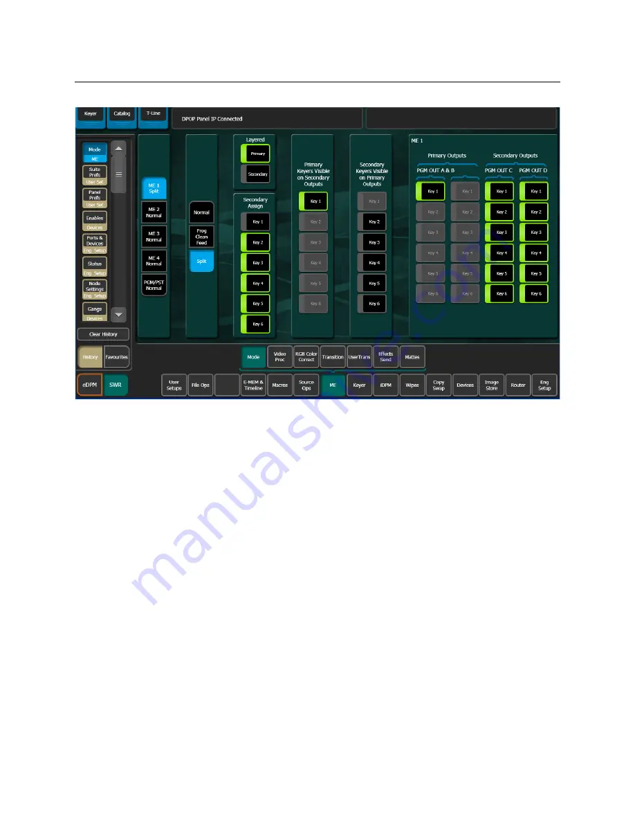
Partition Sync

Partition Sync selects the M/E’s Primary and Secondary partition. The 

Pri

 button high tallies 

red and the 

Sec

 button high tallies green to indicate this mode. Without using Partition 

Sync, there is no way to lock the Pri/Sec mode on, so if you have a Program Clean Feed set 
up on Primary and Secondary partitions for re-entry, and you forget to turn the Pri/Sec 
mode on for that M/E, upon transition the secondary partition would not re-enter as a clean 
feed so the Program Clean Feed would be lost.

Operations

Background and Key Chaining and Partition Sync are configured in the Menu Panel.

With the introduction of GV Switcher DoubleTake, you could Split an M/E and it’s keyers 
between two feeds, for example one feed in English using the Primary Partition and one in 

Содержание Grass Valley GV Korona

Страница 1: ...User Manual VERSION 14 4 071896301 AG 28 June 2019 KAYENNE KARRERA GV KORONA K FRAME Video Production Center...

Страница 2: ...Valley hereby grants permission and license to owners of Video Production Center to use their product manuals for their own internal business use Manuals for Grass Valley products may not be reproduce...

Страница 3: ...ntrol Panel Stripes 24 Touch Screen Menu Panel 24 Basic Single Suite Kayenne Panel System 24 Multiple Suite Kayenne Panel System Example 25 Karrera Control Surface 26 Basic Single Suite Karrera Panel...

Страница 4: ...es 52 About File Operations 54 Introduction 54 About the File Ops Menus 55 GV Switcher File Type Extensions 56 About Show Files 57 About the File Ops All Files Menu 63 Save User Setups 63 Load User Se...

Страница 5: ...e Menu 96 DPM Global Channel Assignments 96 Key Off Control 98 Easy Cube Control 99 Transform Controls 99 Crop Controls 99 Reverse Controls 99 Path Controls 99 Clear Transforms 100 Border Menu 100 iDP...

Страница 6: ...eDPM Definable Sub levels 118 Assign Sources 118 Button Mapping eDPMs to an M E 119 eDPM Mode Menus 119 eDPM Effects Menus 119 eDPM Category Menus 120 File Ops Menu 120 E MEM Timeline Menu 120 Source...

Страница 7: ...137 Macro Button Function Summary 138 Record a Macro 138 Insert a Macro Delay 138 Insert a Macro User Pause 139 Recall a Macro Register from the Master E MEM 140 Pre Attach a Macro 140 Post Attach a M...

Страница 8: ...Setting 158 GV Korona M E Background Button Row Delegation 159 Change Background Buses with Panel Mems 160 Source Rules 160 Create a Source Rules Pattern 161 Store a Source Rules Pattern 161 Apply a...

Страница 9: ...Alphanumeric Keypad 202 Scrolling Lists 203 Menu and Panel Interactions 203 Transitions 204 Wipes 204 Kayenne K Frame Transition Module 206 Perform a Mix Through Video Transition 208 Aux Bus Transiti...

Страница 10: ...Device Associations only into a Register 246 Learning Clips for Devices without Affecting Letter Button Associations 247 About Cues and Ganging 247 Status Display 247 Karrera Device Control 248 Device...

Страница 11: ...rame 271 Modify an Existing Keyframe Duration 272 Restore KF Duration Default to the Keypad 272 About Effect Duration Editing 272 Edit Effect Durations from the Control Panel 272 Edit Effect Durations...

Страница 12: ...96 About Macro Builder 296 About Macro Line Editing 297 Build a New Macro with Macro Builder 299 Edit Macro Builder Created Macros 300 Insert a Macro Delay 301 Insert External Device Control Commands...

Страница 13: ...s and Cropping 326 Create a 4K 2D DPM Effect in 4K SDQS Mode 326 About Corner Pinning 327 Corner Adjust Limits 328 Corner Pinning and Cropping 328 Corner Pinning Menus 329 Create a Corner Pinning Effe...

Страница 14: ...65 Image Store Movie Storage Capacity 365 Image Store Movies Feature Configuration 366 License the Image Store Option 366 Movie Playback from the Menu Application 367 Movie Playback with the System Ba...

Страница 15: ...ive 394 About Image ReStore 394 Image ReStore Button Functions 394 Enable Image ReStore395 Editing Files in Image ReStore 395 Configure a Networked PC for Image Store File Sharing Windows 395 Create a...

Страница 16: ...xvi Table of Contents Index 425 Contact Us 433...

Страница 17: ...des contain information about preparing your site for power installation and cabling The K Frame Release Notes contain information about new features and system enhancements for a specific software ve...

Страница 18: ...t Panel GUI on a touch screen or regular PC including the optional customized keyboard The Switcher Concepts Manual provides an overview of switcher operation and describes basic switcher fundamentals...

Страница 19: ...rface the Soft Panel KSP option and or the Menu application running on a PC Menu on PC In addition the system supports direct control of external devices DDRs Servers and bi directional control to and...

Страница 20: ...el 1 000 E MEM registers with Define E MEM for fine control in creation and editing of effects Optional M E Previewer provides a method to check and monitor any input to an M E VDCP Ethernet connectio...

Страница 21: ...e configured layouts maximum 14 panes per layout and On Air Preview tally K Frame Compact S series Frame Up to 80 inputs and 48 outputs Up to 6 M Es accessible across two suites increased to 12 virtua...

Страница 22: ...so iDPMs can be utilized for more complex effects The Controller M E has a complement of 6 full keyers with Chroma Key and 2D DPMs Up to 16 iDPMs Integrated Digital Picture Manipulators assigned as e...

Страница 23: ...entations Besides a conventional flat surface a special support design permits a curved working surface where the M Es progressively tilt for improved ergonomics CAUTION Do not connect or disconnect t...

Страница 24: ...me system consists of a Control Panel a Menu application running on a touch screen Menu Panel and a Video Processor Frame The Control Panel and Menu application make up a control surface associated wi...

Страница 25: ...el Preferences for configuration of the control panel behavior and independent macro systems to allow for independent building and running of macros by each operator at the control surface Hardware re...

Страница 26: ...epresentative Karrera control surfaces are shown in the following illustrations 8875_20 Suite 1 Menu on PC KSP 1 ME Soft Panel Option Keyboard Included Suite 2 4 ME 35 Kayenne Control Panel Menu Panel...

Страница 27: ...this and many other mounting devices The Menu Panel also has four USB ports two on the right side edge of the panel and two on the back for keyboard and mouse wired or wireless are supported r Transit...

Страница 28: ...a control surface associated with that frame GV Korona Control Surfaces A GV Korona control surface consists of a Control Panel with Source Select Transition Delegation and Master Local E MEM areas an...

Страница 29: ...o Processor The K Frame system can be subdivided into two suites and each suite can have up to two control surfaces Hardware resources in the Video Processor Frame can be assigned to an individual sui...

Страница 30: ...alley Native Protocol for routers routing control systems Trinix Trinix NXT Venus Triton and third party routers Jupiter NV9000 and NV920 and Encore router control systems Tally contact closure K Fram...

Страница 31: ...User Manual Ethernet CPL to control Grass Valley external remote AUX Panels Grass Valley Editor protocol SNMP system monitoring Serial and Ethernet VDCP LDK Series LDX Series camera control with Ether...

Страница 32: ...32 Introduction Supported Control Protocols...

Страница 33: ...try as inputs per shifted row 1st row M1 A M4 A 2nd row M1 C M4 C etc 2nd and 3rd Shift Levels and Delegation buttons Button mappings can be changed in the Button Mapping menu and saved in the User Se...

Страница 34: ...d manually this selection is automatic if a panel has been associated in the Associated Panel data pad in the Eng Setup Node Settings Frame Suite Nodes ID menu The Source Select button scrolling list...

Страница 35: ...Button Mapping 2 Select the PGM PST Bank button notice the Select All button is now available When multiple banks are selected the source delegation will be applied to the same button on each bank in...

Страница 36: ...ined see Define User Colors button list select a color 3 If a user color is selected you can adjust the RGB color by using the Menu Panel knobs or clicking in the data pad and entering a value in the...

Страница 37: ...button default is colored text over a dark background Define User Colors The five User Color buttons allow you to create custom colors for Source Source Colors menu and Delegation Panel Color Scheme...

Страница 38: ...stallation Service Manual for more information 1 Select Eng Setup Node Settings Remote Aux Button Map 2 Select an individual Remote Aux Panel by selecting its button in the left pane or select the Mul...

Страница 39: ...hanges the button mapping for all the selected Remote Aux Panels 1 Select Eng Setup Node Settings Remote Aux Logical Map 2 In the Panel Delegation area select a Remote Aux Panel button 3 In the Logica...

Страница 40: ...40 Panel Preferences Map Remote Aux Panel Delegation Buttons Logical Mapping...

Страница 41: ...uite Signal Type parameters and enable disable Re Entry Aux Bus Transitions See Aux Bus Transitions on page 209 About Suite Signal Type HDR Mode K Frame systems transmit Payload ID parameter values ba...

Страница 42: ...international programme exchange Colorimetry Rec BT2020 ITU R BT 2020 2 10 2015 Parameter values for ultra high definition television systems for production and international programme exchange Colori...

Страница 43: ...them connect devices properly Production personnel on the other hand are interested in the content they work with for their shows and are generally not concerned about which individual device or rout...

Страница 44: ...rolling list has more Logical IDs than physical inputs These can be used to permit alternative processing of the same incoming signal For example the same camera input can be assigned to two Logical I...

Страница 45: ...rol Panel An OLED Name appears only on the Source Name Displays on the Control Panel Up to eight characters are displayed A Menu Name is limited to eight characters and appears on all the GV Switcher...

Страница 46: ...hing and Effects Portability Source patching makes it possible to build effects on a GV Switcher system in one facility or truck and then use those effects on a different system at another facility th...

Страница 47: ...cal IDs 1 Select User Setup Suite Prefs Source Patch 2 Select the Eng Sources Fixed Sources button to select a source type 3 Select the Logical ID of the source you wish to change by either Selecting...

Страница 48: ...ameters for Video Processing and RGB Color Correction in the Source Correction menu Patch a Key Input from Another Source You can patch a key from a different source using Patch Key 1 Select User Setu...

Страница 49: ...ault Keyframe and clears the source memory to the default settings for sources selected on enabled levels The Default Keyframe menu is used to learn the current Control Panel state to the system s Def...

Страница 50: ...the left select the M E or Switched Preview that will be affected by the settings on the right Each M E has Primary and Secondary Preview parameters for Safe Area and Crosshairs and an M E Viewer lay...

Страница 51: ...view or Aux Buses to each video window Multiviewer menu preferences are saved as part of Suite Prefs and can be loaded or excluded as part of the Load Granularity in the File Ops Eng Setup menu Prereq...

Страница 52: ...more than one Multiviewer acquired press the Identify button to display the available Multiviewers in the top middle of the monitor so the correct Multiviewer will be selected for adjustment 3 Select...

Страница 53: ...me in the Menu column of the Source Patch menu to change the window name a With the source assigned and the window selected in the Multiviewer Prefs menu note the Source Number in the upper right data...

Страница 54: ...on to another without affecting the current operation File information is loaded to the switcher system RAM and this immediately affects system operation and resources Drive Access File Operation menu...

Страница 55: ...ups of files routinely used together for a particular production Save important files to the Menu Panel hard drive and a USB Memory Stick for backup clearly label each perhaps including the date and s...

Страница 56: ...ory Up Directory and Open Selected or double touch click on the file icon buttons 2 Select the file icon s to highlight it 3 Select the Delete button Create a Folder 1 Select the Create Folder button...

Страница 57: ...rom the Show Files menu Show File Buttons Create Show opens a create show pane In this pane you enter the name of the Show select the Show Name data pad and if you choose disable or enable switcher pr...

Страница 58: ...the Show file so it is not a cumulative load overwrite Select All toggle button selects or deselects all the available preferences and settings Create saves the show into the currently selected direc...

Страница 59: ...t a register data pad and enter values using the pop up keypad 5 Select the Create button in the Create Show pane CAUTION The Eng Setup button lower right of menu is off by default because ports and s...

Страница 60: ...he default is all 5 Select the Create button in the Create Show pane to load the Show file not the Load Show button as this will load the entire Show file without your selections Load a Show from the...

Страница 61: ...61 Kayenne Karrera GV Korona User Manual Update a Show File 1 Select File Ops Show Files...

Страница 62: ...button will be inactive 5 To change the registers loaded select the register data pad left of each button and enter a series or range of registers to be included in the Show file the default is all 6...

Страница 63: ...Name and Reverse Order reorders the current sort to ascending or descending buttons and manage all files types in the System and Remote Storage menu tab directories Use the Utilities pane buttons to p...

Страница 64: ...orage menu tab left side of menu navigate to the folder you want the User Setup to be saved 4 Optionally enable or disable preferences and settings or enable the Select All button in the Load Granular...

Страница 65: ...Source Tables or Source Rules Save operations for the Source Tables and Source Rules menus are identical Saving Source Tables will be described in this example 1 Select File Ops Source Tables CAUTION...

Страница 66: ...navigate to the folder you want the Source Tables file to be saved 3 Select the Save button in the File Operations pane Load Source Tables or Source Rules Load operations for the Source Tables and Sou...

Страница 67: ...wever the Register function buttons in the center of the menu and others in the File Operations pane are unique to register based menus Register files are named by their bank and register number For e...

Страница 68: ...ies Start Register when enabled allows you to start one or a multiple registers at any register number Subsequent registers will be offset from the Start Register value Save Files in Register Based Me...

Страница 69: ...he registers to be loaded 3 Select All or enter specific registers or a range of registers and or a start register 4 Select the Load button in the File Operations pane Load Registers with an Offset Us...

Страница 70: ...Eng Setups 2 In the System or Remote Storage menu tab left side of menu navigate to the folder you want the Engineering Setup to be saved a In the Load Granularity pane enable or disable preferences a...

Страница 71: ...e Prefs button in the center menu pane and in the Load Granularity pane enable or disable preferences and settings that will be loaded as part of the user setups 5 Select the Load button CAUTION The L...

Страница 72: ...72 Suite Preferences Load User Setups...

Страница 73: ...Example Keyers are used to insert part of one picture into another to create a composite picture Keying involves three signals background key cut used to specify where to cut a hole in the background...

Страница 74: ...suppression off Changes Opacity temporarily to 100 to permit an accurate backing color sample and then returns it to its original setting Sets Key Position and Size values to default 0 Two different A...

Страница 75: ...line on the waveform display but this never occurs due to set lighting variations shadows etc This means you will need to pick the best suppression for the overall look of the key You can select the...

Страница 76: ...e chroma key hard and noisy When not enough highlights will be added to the background Note that incomplete luminance suppression is not necessarily bad The highlights added to the background will mat...

Страница 77: ...re Auto Setup 1 Press one of the keyer transition buttons on the Control Panel for example Key 1 on an M E to delegate the keyer you wish to use 2 Choose the selected keyer s key bus that has the chro...

Страница 78: ...ay improve the key so that Reshape is not needed 1 If you decide you must use Reshape follow the Auto Setup procedure in Configure Auto Setup on page 77 but select Reshape in the Keyer menu to turn it...

Страница 79: ...or Clip Low may be set improperly If adjusting these parameters fails to solve the problem you should consider activating the Reshape feature Apply Chroma Key Secondary Color Suppression Secondary col...

Страница 80: ...ept as wide as possible You should only narrow selectivity increase its value if you cannot avoid changing opaque areas of the foreground 3 Adjust the secondary Angle so that changing secondary Chroma...

Страница 81: ...button 3 If not already selected select the Base Color data pad of the desired Background 1 or 2 Use the top three soft knobs to adjust Base Hue Base Saturation and Base Brightness of the base fill co...

Страница 82: ...e information Setup a key patch an implicit split key This split key is used whenever that logical source is selected and adds operational flexibility see Patch a Key Input from Another Source on page...

Страница 83: ...ck in the Current column then use the Top Move Up Move Down and Bottom buttons on the left to place the key in the desired location The key priority order changes immediately as a cut Transition Betwe...

Страница 84: ...escribed in Transition Between Different Keyer Priorities on page 83 6 Set up the Next priority stacking order selecting the keyers in the Next column and then using the Top Move Up Move Down and Bott...

Страница 85: ...combination for example you can use the fill from Keyer Video Source Frame Store 1 with the cut from Keyer Cutout Source Frame Store 2 You can even use the Live video from the Keyer Video Source and...

Страница 86: ...Use FS 1 V K or Use FS2 V K to select the Video and Key source image or a Select the Keyer Video Source for the fill b Select the Keyer Cutout Source for the key cut Set a Pattern Mix You can combine...

Страница 87: ...ll now show the combined Mix 1 and Mix 2 pattern 9 You can select the type of pattern mix with the Mix type buttons Mix NAM NAM The NAM buttons are used for And or Or pattern mixing 10 You can also ad...

Страница 88: ...r Borderline settings Keystore settings Background sources Aux sources Learn Source Memory for a Keyer 1 Select a source on a keyer bus and setup the keyer with the desired settings using the Control...

Страница 89: ...2 Select Keyer Mode in the menu and select that keyer The Source Memory button will be illuminated 3 Select the Source Memory button The Source Memory window appears 4 Select the Delete button The So...

Страница 90: ...Changes to keyer source settings with Source Memory learned do not auto update If you make a change you must repeat the steps above to learn Source Memory Source Memory can only be deleted from the G...

Страница 91: ...pane 3 Select a full M E resource in the Physical Resources pane Release Acquire DPM Resources between eDPMs iDPMs 1 Select Eng Setup Acquire Resource 2 In the Physical Resources pane release and or a...

Страница 92: ...Kayenne Karrera GV Korona Installation Service Manual Enable DPMs on the Kayenne Control Panel 1 From the Kayenne K Frame Control Panel in the MFM Multi Function Module Home menu press an ME button 2...

Страница 93: ...ontrol Panel in the Modifier Area press the eDPM button 2 The acquired eDPM channels are available in the keyer row displayed in cyan blue when delegated eDPM channels are always enabled 3 Press a cha...

Страница 94: ...l DPMs four DPMs per dual M E board DPMs are licensed in pairs Kayenne K Frame provides two DPM options iDPM Full DPM including transform engine for complex effect manipulation up to 16 iDPMs can be l...

Страница 95: ...space 3dLc X Y and Z 3D Locate ROT Rotate SPIN Spin Axis Locate Axis ASPT Aspect SKEW Skew PRSP Perspective 2DLc Post Transform X Y and Z locate in 2D space The PGLB Primary Global and SGLB Secondary...

Страница 96: ...e Menu The Transform menu contains a data pad matrix in the upper left for delegation Data pads for keyers with DPMs assigned will be active Inactive keyers will be grayed out Select an active data pa...

Страница 97: ...n effect with three keyers assigned to DPM channels on an M E and selected those keyers and applied a Spin transform all three keyers would spin independently around their own axis simultaneously But...

Страница 98: ...menu is used to turn off the key signal processing for the delegated keyer resulting in a full raster image For example suppose you want to fly a graphic that is normally accompanied by a key signal T...

Страница 99: ...inate system for reference Selecting the Target button provides image adjustment using the screen as the reference Only one space button is selectable at a time Crop Controls The Crop On button locate...

Страница 100: ...der for each licensed iDPM eDPM and 2D DPM The borders are added outside of normal blanking This means that when a border is added it does not crop into the original image so a border can be added to...

Страница 101: ...llow Image is selected crop values of the shadow match the crop values used for the primary image Only shadow edge softness controls are active in this mode When the Crop Softness data pad is selected...

Страница 102: ...ation of the color of the matte is shown at the bottom of the pane Use these controls to adjust the color of the Glow Glow Path Control Pane Controls for glow path using the standard Hold S Linear Lin...

Страница 103: ...odulation controls Modulation Pane In the Modulation pane you select the wave train axis Horizontal or Vertical for which the rest of the menu controls will apply The following Soft knob controls appe...

Страница 104: ...e Turn is a transition effect with the video being mapped to an original plane a cylinder and a final plane parallel to the original plane Page Roll maps the video to an original plane and a cylinder...

Страница 105: ...he Split Axis Position data pad brings up Horizontal and Vertical soft knobs that control the location of the split Ripple Mode Ripple is an effect in which the source video mapped to a plane is effec...

Страница 106: ...rce video to be mapped Select the Sphere Kurl Mode button to access the sphere controls The following soft knob controls are available Size defines the radius of the sphere before it is modified by As...

Страница 107: ...eflect multiple sides by turning on the Mirror Top Mirror Right Mirror Left and Mirror Bottom buttons The original picture for that side is always reflected A side that has been mirrored to the opposi...

Страница 108: ...eable Some extremely low lighting values particularly Light Softness when used in combination with other lighting values can create visible artifacts stair step aliasing Due to the intricate lighting...

Страница 109: ...At 100 the lighting acts like it is reflecting off of a mirror At 0 the light acts like it is reflecting off of a frosted piece of glass Flare When light reflects off a surface two lighting component...

Страница 110: ...up keypads The menu is accessed by selecting iDPM Output Recursive Output Recursive Presets The Output Recursive system has a set of presets that can be selected to simplify creating effects with Outp...

Страница 111: ...soft knob parameters are also displayed in the Appearance data pad Picture Decay causes the frozen image in the Output Recursive to fade away evenly over time Star Decay causes random pixels of the f...

Страница 112: ...ttons set the type of strobe effect that will cause the automatic capture of the new image None turns Strobe Off Time freezes a new image at an adjustable time interval normal strobe Keyframe freezes...

Страница 113: ...ook like particles Soft Knob Button Group Picture Decay causes the frozen image in the Output Recursive to fade away evenly over time Star Decay causes random pixels of the frozen image in the Output...

Страница 114: ...matte Matte allows you to create a matte fill for the montage and activates the Hue Saturation and Brightness soft knobs for modifying the matte Rainbow allows you to create an alternating RGB rainbow...

Страница 115: ...elect button for multiple keyers 3 Turn on DPM Borders by selecting either the Square Border or Round Border button in the Border Enable menu pane 4 Select a path type by selecting the S Linear Linear...

Страница 116: ...of the four keyers on PGM PST and key the composite of DPMs or Apply an additional transform to the composite with a PGM PST iDPM on any of the first four keyers and transform the entire composite eD...

Страница 117: ...executed before eDPM timeline eDPM Partitioning The eDPM partition boundary is a sub level in the eDPM Primary partition The Select All EDPM Pri and EDPM Sec and PART buttons are used to enable disab...

Страница 118: ...sub levels in the Master E MEM Timeline for M E 3 Using definable sub Levels allows for the recall of eDPM effects from Local E MEM For example effects created for M E 1 can have the eDPM definable s...

Страница 119: ...tical to the iDPM Transform menu DPM Transform Menu on page 96 in all ways except the ME Keyer selection matrix upper left pane is replaced with the six channels of the eDPM however the functionality...

Страница 120: ...enu allows you to create folders and save load and manage the 1000 eDPM register files and all files To access the eDPM File Ops menu select File Ops and either the eDPM or All Files menu button The e...

Страница 121: ...e selection for eDPM Channels using the scrolling list with Lock button at the right of the menu Select Source Ops eDPM to access the menu Picture Menu The eDPM Picture menu provides controls for the...

Страница 122: ...imary Partition is made up of output eDA and eDC for the Secondary Partition Also as with iDPM the eDPM channel on the Primary Partition can be made visible on the Secondary Partition and vice versa s...

Страница 123: ...areas in seconds frames odd field format using the button the separator indicated below as and pressing the hard button below Enter in the display to complete the entry seconds frames field Enter The...

Страница 124: ...rn more about E MEMs work buffers and registers see the Switcher Concepts Manual at grassvalley com Learn a Register in the Current Bank To learn registers in the current bank from the Control Panel 1...

Страница 125: ...ine Register Ops menu To recall an E MEM register press the following 1 Page button if necessary 2 Button for the desired page 0 100 900 3 BNK Bank button 4 Button of the desired bank 5 Keypad button...

Страница 126: ...ges the delegation to Master E MEM button colors change and M Run is displayed in the OLED below the right most button Press and hold again to return to Local E MEM Press any E MEM button in the deleg...

Страница 127: ...the desired effect the effect will run as soon as it is recalled Learning E MEM Sequences Learn a Sequence of E MEM Registers 1 Press LRN Lrn SEQ Seq 2 Press the Page Bank and Register number keypad b...

Страница 128: ...hand affects only the specific elements involved in the recording of that macro For example a macro can be recorded that sets up only the Preset bus with a particular source and selects a specific wip...

Страница 129: ...a macro button with the same macro register delegated or attached on CS B and vice versa A macro run from CS B with a User Pause can be resumed by pressing a button with the same macro register delega...

Страница 130: ...out Playing a Macro from the Control Menu Important For all groups The latest macro played from the menu will be displayed in the far left player of the control surface you are logged into and Previou...

Страница 131: ...urce button rows 2 M E 2 key rows 4 shift levels 22 source buttons for macros 352 macros Macro registers can be saved to disk and reloaded making the total number of pre made macros available to a GV...

Страница 132: ...nu the right arrow will resume a paused macro from any player group For example if you are logged in as Suite 1 CS A selecting an E MEM Player right arrow button for a stopped macro does not simulate...

Страница 133: ...h Macro Attachable enabled will have the Macro Attachable panel preference disabled the 9 1 or newer default when imported The show can be updated to the previous state by enabling the Macro Attachabl...

Страница 134: ...eletes the macro associated with that button When macro mode is on pressing the Repl Attach button activates attach mode You then select the macro register of the desired pre defined macro and press t...

Страница 135: ...played in the source select OLED third button from the right Control Panel Macro USER Button in Macro Delegation 6 Press USER to insert a User Pause 7 If desired perform any additional actions to be r...

Страница 136: ...ch the macro will be attached if Show Attach is on the panel button will flash Post Attach a Macro A post attached macro means the macro will execute after the mapped function of the button Generally...

Страница 137: ...ton will turn blue and blink slowly until a macro is selected 2 Press the macro register button on the delegated keyer row of an existing macro to which you wish to append additional steps The Record...

Страница 138: ...button deletes the macro associated with that button When macro mode is on pressing the Replace button activates attach mode You then select the macro register of the desired pre defined macro and pr...

Страница 139: ...ource Select module to delegate the module 4 Press a macro delegated button to start recording 5 Perform any actions to be recorded as part of the macro before inserting the User Pause 6 Press Insert...

Страница 140: ...l flash Post Attach a Macro 1 Delegate the bus rows to Macro by pressing the Macro button on the Control Panel 2 Press and hold down a Control Panel button for the attachment 3 Press the macro button...

Страница 141: ...and blink fast indicating a Macro is being recorded 3 Perform the additional steps using the Control Panel and or the menus 4 Complete the append by pressing the blinking Record button or pressing th...

Страница 142: ...ssing the Macro register button again Macro Delegated Row Buttons 1 Press the Macro button in the Delegation area located above the Source Select area of a Stripe the button row above the OLEDs is now...

Страница 143: ...the macro to resume Result Once completed the macro button high tallies the macro color yellow is the default Resuming a Paused Macro Buttons delegated to macros or with macros attached in a paused st...

Страница 144: ...he newly defined macro button will flash until Show Attach is turned off Attach Multiple Macros to the Same Button Up to three macros one of each type attached pre attached and post attached can be at...

Страница 145: ...rea with an existing macro and press the register button 3 Perform the additional steps using the Control Panel and or the menus 4 Complete the recording by turning off the Append button or by pressin...

Страница 146: ...mber in the Local E MEM area when the Macro menu is delegated by pressing the Macro button in that M E 1 Select Macros Catalog in the menu 2 Select the Panel Name data pad next to the desired macro re...

Страница 147: ...r Manual Insert a Macro User Pause from the Catalog Menu 1 Select the Macros Catalog menu 2 Enable the Record button and press the Right Arrow button to begin recording 3 Select the User Pause button...

Страница 148: ...the Macro Editor A macro User Pause can be inserted and edited with Macro Editor See the Kayenne Karrera GV Korona User Manual for Macro Editor operations 1 Select Macros Catalog 2 In the Macro Edit...

Страница 149: ...om Pause command resumes a paused macro from E MEM 1 Select Macro Catalog Macro No in the Macro in E MEM button pane 2 Select the macro then Run From Pause Note Without a Run From Pause command learne...

Страница 150: ...elect E MEM Command Learn a Select E MEM Command The Select command stops a running macro and starts it at the beginning using E MEM 1 Select Macro Catalog Macro No in the Macro in E MEM button pane 2...

Страница 151: ...ton upper right 4 Select the menu button for the macro register to be attached 5 If desired name the macro by selecting the Name data pad and entering the name in the pop up keyboard Press Enter Playi...

Страница 152: ...All Enter Reg s or the Select Reg s buttons enter or select a range for the latter two 5 Select the Save button Loading Macro Registers Macro registers are loaded by selecting the macro register file...

Страница 153: ...rom the mismatched E MEMs and macros E MEM Recalls in a Macro The state of the Effects Dis and SEQ buttons are sent as part of each E MEM recall command When recording E MEM recalls to a Macro make su...

Страница 154: ...e Run From Pause command resumes a paused macro from E MEM 1 Select Macro Catalog Macro No in the Macro in E MEM button pane 2 Select the macro then Run From Pause Note Without a Run From Pause comman...

Страница 155: ...d Utility buses can be delegated for control to a Source Select button row On the Kayenne Control Panel Aux bus and Router modes can also be delegated Source Select Button Row Mode Descriptions Mode S...

Страница 156: ...mode button Source Select Button Row to Aux Mode Delegation Source Select button rows can be delegated to Aux outputs on the GV switcher Control Panels that can for example be assigned to monitors Im...

Страница 157: ...egation on page 155 from Aux outputs to Macro registers with a P MEM recall There are 99 P MEM registers available numbered from 1 to 99 P MEMs learn Source Select button row mode delegations for E ME...

Страница 158: ...this point Keypad buttons 1 through 5 5 for Aux are toggle buttons high tally is on Enable or disable Stripes and or press Enter to continue 3 Press 0 9 in the keypad or the dot button to select the...

Страница 159: ...s A or Sec for bus C 2 For the Secondary bus row press and hold the Secondary Delegation button and press Pri for bus B or Sec for bus D GV Korona Background Bus Button Row Delegation If the Delegate...

Страница 160: ...ill be set up so that the desired Keyer status will result after the transition is performed No user intervention is required because Source Rules will have been applied logically However Source Rules...

Страница 161: ...s state buttons in the Source Rules Setup menu pane for each Keyer you wish to set the state Store a Source Rules Pattern 1 Select one of the Store 1 6 buttons to store the Source Rules Pattern 2 To n...

Страница 162: ...or example if there s a special camera only used for the primary customer s feed a Linked bus used for a secondary customer s feed might select a wide shot whenever that camera was selected on the Con...

Страница 163: ...Bus Links menu to link enable disable break and choose the source table for bus links Standard Table All Sources 1 to 1 is the default Source Table Selected Controller bus and Linked bus buttons turn...

Страница 164: ...lso you are able to create named relationships between the source table and the bus links to which they are assigned The Standard Table All Sources 1 to 1 Source Table is the default One of the other...

Страница 165: ...g a Source Table data pad selecting the Rename button and entering a new name 3 Select a source in the Linked Source column of the Source Link Source scrolling list the Table Setup pane 4 Select the s...

Страница 166: ...e Tables column becomes available Select another source table for the bus link Source Table File Operations Source Tables are part of GV Switcher file operations File Ops Source Tables menu You can pe...

Страница 167: ...and Aux 1 Aux 2 and M E1 Key1 are all linked in parallel to PGM A 1 Select the Controlling Bus data pad in the Table Setup pane the Controlling Bus selection menu is displayed 2 Select the M E Buses...

Страница 168: ...ple In the menu example below Controller PGM A controls Linked Aux 1 Linked Aux 1 is the controller for Linked Aux 2 and Linked Aux 2 is the controller for Linked Aux 3 Button Color Definitions The fo...

Страница 169: ...ing Rules and Restrictions The Switched Preview Primary Preview and Image Store input buses cannot be configured as Linked buses An Aux bus associated with a DPM cannot be configured as a Controlling...

Страница 170: ...its Links This control affects the behavior of the Control Panel Hold button for all Linked buses When Bus Hold Inhibits Links is On and the Hold button on a Linked bus is also On that Linked bus will...

Страница 171: ...d during live operation for fast real time control The Menu Panel for Kayenne and Karrera and the built in touch screen for GV Korona K Frame are generally used in conjunction with the panel controls...

Страница 172: ...module configuration options refer to the Kayenne Karrera GV Korona Installation Service Manual 4 M E Control Panel and Modules Other Control Panel configurations are available for the Kayenne system...

Страница 173: ...and keyer delegation and status Next Transition Element buttons Next Transition Type buttons Cut Auto Transition buttons with Trans Rate display Transition Preview and Preset Black buttons Keyer trans...

Страница 174: ...bar graphs similarly track the percentage of completion of the transition per partition in Split Mode The Lever Arm can be split into two separate arms to allow each partition to be transitioned separ...

Страница 175: ...ows Auto and Key Mix 1 6 buttons having an associated transition rate to be altered set or queried Once the Trans Rate button is selected the associated buttons flash and the Local E MEM Module change...

Страница 176: ...y of the eight transition element buttons and then select one or more of the remaining buttons The rule is that while any next transition button is held down other next transition buttons can be added...

Страница 177: ...cessed by pressing the following buttons EMEM Local M E E MEM recall and edit mode DELG Change M E control on selected Stripes Panel Mem Learn and recall panel memory Trans Rate Set transition rates f...

Страница 178: ...he Bank buttons BNK 0 BNK 3 have been placed in the Master E MEM Module right side of keypad to provide faster access to banks A single press of the button delegates to the bank indicated a DPOP of th...

Страница 179: ...Run effects buttons Just left of the Bar Display is the Jog Enable button enables the Jog Knob and the Pause Stop Next and Rew effects function buttons In the center are the Level buttons with display...

Страница 180: ...cting Wipe 1 or Wipe 2 in any Transition Module Last button far right Toggles between current and previous delegation modes HOME button only displayed when not at the Home position Moves the display t...

Страница 181: ...Source Select Module is available in three configurations 15 25 and 35 button models Source Select Module Example Text Display Outlines Outlines border the display text this is the default Outlines ca...

Страница 182: ...Module organization for source select buttons Source Selection buttons left Can be mapped and delegated to buses macros routers etc and there are no limits to mapping so the same function or source ca...

Страница 183: ...ons Hold button Sets a bus hold on the delegated row M E bus select buttons K1 K6 A B U1 and U2 in columns 2 4 pressing one of these buttons delegates that bus Macro select button Delegates rows 1 and...

Страница 184: ...tons displays the current delegation of the panel row to the logical M E M E 1 M E 2 PGM etc Split OLED Source Select Display States Control Panel Source Select OLED displays split under the following...

Страница 185: ...ce then the number 3 would wrap 3 to the next line of the OLED button display The Local Aux Module is similar to the Source Select Module the main differences are Status displays OLEDs are located bet...

Страница 186: ...trols pressing a button on the top row selects an Aux Bus destination and pressing a button on the bottom row selects a source for the selected top row Aux Bus System Bar The System Bar provides Switc...

Страница 187: ...the currently selected source on that Preview Prime bus is routed to the Switched Preview output When the Local Aux Module has also been delegated to PVW Pri any source mapped on the Local Aux Module...

Страница 188: ...the clip currently loaded or a cue command if the clips are the same Play button Sends a Play command to the selected device pressing Play a second time pauses the device Display Displays the current...

Страница 189: ...Device Control Module and when selected show status for that device in the Status Display top left Status Display located middle right at the top right of the Device Select button group Run Control b...

Страница 190: ...at its maximum shuttle speed and Var Starting from a pause condition the first 360 degree forward rotation of the Jog knob scales play speed from zero to 1 0 then the next 360 degree rotation scales...

Страница 191: ...activates any object on a Stripe the Multi Function Module will automatically delegate to control the specific object involved For example selecting a key for the next transition automatically delegat...

Страница 192: ...the menu delegation a second button press is not required SPOP stands for Single Press Open SPOP buttons operate similar to DPOP but only a single button press is required DPOP Buttons with Menus DPO...

Страница 193: ...u controls displayed on the screen The screen is designed to work with a finger or other soft object The touch screen is sensitive to a single pressure location only so only one touch surface control...

Страница 194: ...is selected the selection causes the rest of the screen to display settings and controls for that keyer A special pattern data pad also exists which displays the shape of the current pattern the squar...

Страница 195: ...g the joystick will change the values 1 To select a parameter for joystick control white select any data pad with a dot and press the soft knob for that data pad text and dot turn blue 2 Move and turn...

Страница 196: ...Screen Organization and Components For clarity the menu screen examples are divided into two areas Navigation and Content and Messaging Quick Link Tabs Scrolling History and Favorites list Menu Categ...

Страница 197: ...Selected Delegation Selected Mode Touch Buttons Additional Function 6x5 Six Keyer Data Pads Operations Status Notification Area Mode Selection Button Group Soft Knobs Label and Data Pads Data Pad Touc...

Страница 198: ...ccessed by clicking on the representative menu Icon The scrolling menu icon window can be cleared by selecting the Clear History touch button left side of menu History menu icon buttons appear light b...

Страница 199: ...reate a Favorites list perform the following steps 1Choose a Favorites page 1 10 using the Left and Right menu arrow buttons 2Navigate to the menu to be added to the list 3Select a grayed out or exist...

Страница 200: ...ion to the History and Favorites mode Each tab with a label provides a semi transparent predetermined menu that appears over the current menu when touched to allow fast access when performing operatio...

Страница 201: ...s like the Keyer menu for example because it must control all keyers This highest level of delegation is located on the left side of the menu as a grid of data pads Data pads display limited status fo...

Страница 202: ...or other single numeric parameter pad brings up a numeric keypad that can be used to enter exact values You can also use a standard computer keyboard to enter information while this display is active...

Страница 203: ...m currently associated with it on the right list You can then choose a different item from right list to change the association Some of these menus have a Lock button for the right list This prevents...

Страница 204: ...is changed to a new object that object s current status which may have been changed since last shown will be reflected on that panel Transitions A transition is a change from one image to another The...

Страница 205: ...6 Vertically more than 23 or X or Y more than 14 may result in on screen artifacts or anomalies Modulation Multiply and Horizontal Split functions are not supported Rotation can be used successfully w...

Страница 206: ...ive keyers will transition from on air to off air or vice versa Background transitions will occur between the A and B buses with a flip flop at the end of transition ensuring the A bus is always on ai...

Страница 207: ...lect the new source to transition to on the B bus If you are transitioning in a new key select that new source on the key bus If you are changing key priority specify a new key priority in the Keyer P...

Страница 208: ...E Mattes menu select the ME for the transition left pane 2 Select the Base Color data pad right pane 3 Set the Brightness to 100 and the Saturation to 0 with either the soft knobs or the popup keypad...

Страница 209: ...e any corresponding darker areas of the previous picture During the second half of a NAM transition the previous picture mixes out of the darker areas of the new picture FAM transitions also first fad...

Страница 210: ...ix or wipe as the transition type for the selected aux bus repeats when a source is taken on that aux bus By turning on the Trans Lock button the transition will continue to mix or wipe until it is de...

Страница 211: ...ux bus can then use the resource as it frees the resource after the transition When resources are allocated the ME Mode menu still allows for the keyers to be used on the resource If keyers are cut on...

Страница 212: ...the Application column 4 To change the transition rate press the Aux Transition Rate parameter button enter a transition rate in the pop up keypad and press Enter The Mix and Wipe buttons on the Loca...

Страница 213: ...e Control Panel on page 234 Karrera Device Control on page 248 and Device Control with GV Korona on page 249 The Enables Control and Events List Device menu features include ChyronHego Click Effects P...

Страница 214: ...s must be disabled either by selecting the Disable Selected or Disable ALL buttons or from a loss of communication before they can be enabled Timeline Events Menu The Timeline Events menu allows you t...

Страница 215: ...P Ethernet VDCP Serial DDR Odetics DDR BVW VTR BVW Status Device icon when provided from manufacturer Device type Clip loaded Cue Time Command Play Stop Gang Enabled Disabled Loop Enabled Disabled Con...

Страница 216: ...ts Clears enabled buttons data pad entries and loaded clips for the selected point of use Device Summary Clear All Events Clears enabled buttons data pad entries and loaded clips for all Device Summar...

Страница 217: ...LyricX however they will be available for other AMP devices Devices Timeline Events Menu Buttons Click Effects PRIME Lyric Button Description Device Summary point of use Select to enable Engineering...

Страница 218: ...ys folder and scene file operations menu activate scene for control and to identify the active scene when layered on one channel In Take scene Out Take scene off air Note To cue the same scene again a...

Страница 219: ...ns ClipStore DDR Button Description Device point of use Selection displays Device Picker Engineering name Device name Status Device icon when provided from manufacturer Connection status bar Time Code...

Страница 220: ...t frame is played Progress bar Percentage of clip played Record Enable Begin recording source Record Time Enable record time select data pad to enter Record Time duration Mute Mute clip audio for the...

Страница 221: ...rt controls for devices Clip Scene Browser Menu Pane Buttons Button Description Current Folder Select to open Current Folder operations menu graphic devices supported in an upcoming release View List...

Страница 222: ...st Cut Cut a Event List selection Copy Copy Event List selection Paste Paste copied cut event to Event List Move Up Move Event List selection up Move Down Move Event List selection down Save List Save...

Страница 223: ...on the GV Switcher Devices menus If the folder list or clip list are incomplete re enabling the device will fetch the entire folder and clip list A maximum of 20 folders is recommended along with a m...

Страница 224: ...ues will result in no change between keyframes But for events this same practice will result in reissuing the event at each keyframe It is a good practice to use the Clear All Events or Clear Delegate...

Страница 225: ...e Selected button or enable all using the Enable All button in the Enables pane Control an External Device Example 1 Go to the Timeline Events menu select the Clear All Events button This ensures only...

Страница 226: ...to the desired state making sure the DDR source is not selected on the PGM PST A bus 2 Learn this state to an E MEM register as the first keyframe of the effect 3 Go to a point later in your effect g...

Страница 227: ...y signal and select Load and Cue events for it 4 Set up the Control Panel so PGM PST Key 1 is not on air and the DDR source is not selected on the PGM PST A bus 5 Add this to the first keyframe of the...

Страница 228: ...and modifies what happens when a clip in the browser is selected This allows an event list to be built by turning on Insert After then selecting clips in the order they should appear in the event lis...

Страница 229: ...l device typically requires spacing the instructions over two or more keyframes The space between keyframes allows the device to respond to the first set of instructions For example a DDR or VTR takes...

Страница 230: ...red on the timeline The device may not play if it has not fully cued when the effect is run It is up to the operator to build the effect to accommodate cue and load time Also running effects with exte...

Страница 231: ...send commands from the Control Panel or menu to your external device You can take IDs fire up to four GPI sets clear buffers and override or fine tune the controls 1 Select Eng Setup Ports Devices Ex...

Страница 232: ...ta pad and entering an ID and selecting Enter 3 Select Take ID 4 Optionally select Next to take the next ID in the list repeat to take the next ID and so on 5 To clear the buffers either select the Cl...

Страница 233: ...Extended pane to set controls for IDs Buffers and Layers Fire XPression GPI Sets There are four XPression GPI Sets that can be fired from the GV switcher GPI Set 1 GPI Set 4 There is macro support fo...

Страница 234: ...Enter Repeat for each GPI Set preset 3 Select one of the GPI presets then select Fire GPI You can also create a macro to select and fire the GPI preset ID from the Control Panel or Macros menu Kayenn...

Страница 235: ...list per device to be brought into the Status Display window Local Aux Module Ganging The Gang Control function in the Local Aux Module allows a single point of control for multiple devices The points...

Страница 236: ...le Panel Gangs Local Aux Bus gangs can also be controlled with the optional Device Control Module Stop Play Rew Fast Fwd Forward Jog Reverse Jog Mark etc are operational in Gang mode see Device Contro...

Страница 237: ...s the right most Device Control group on the System Bar see System Bar on page 235 The current device is shown in the function button status display just below the Joystick on the right side of the Mu...

Страница 238: ...to the Event List in the 1st 2nd or 3rd position in the list using the bottom three soft knobs All other clip names will be pushed down one Insert a clip 1 Turn the soft knob Clip 1 Clip 2 or Clip 3 a...

Страница 239: ...nt folder on the selected device and select a clip editing buttons appear in the main function area b Press the DEL button on the Multi Function Module The clip name will be deleted from the Event Lis...

Страница 240: ...nction Module in the Multiple Device mode Each device name is displayed above the assigned button D1 D2 D3 etc The PLAY CUE and STOP command buttons tally as follows PLAY button high tallies green whi...

Страница 241: ...erations Enter the timecode 1 Press the GOTO button 2 Enter the timecode using the examples below 3 Press the ENTER button The Multi Function Module returns to Device Control mode Examples of Timecode...

Страница 242: ...n channels for example Video and Key and driving video walls with 4 or 8 channels Ability to record a clip to a device cue to mark in and add a play command Cue can be for more than one device Variabl...

Страница 243: ...k In etc are performed simultaneously for all devices in the gang Loading clips which is not motion control is not included in a gang To load more than one device at the same time use a Q MEM linked c...

Страница 244: ...also affect gang selections made in the Local Aux Bus Module and vice versa About Q MEMs Q MEM can be used to assign a device to a letter button on the DCM load a named clip on that device and cue to...

Страница 245: ...isters The selected Cue register button high tallies red Learning a Q MEM Register with Multiple Devices Lettered button A F links can be learned as part of a Cue register for later recall 1 Press and...

Страница 246: ...as part of a Cue register all devices will play when the register is recalled Learn Device Associations only into a Register Cues can be used to associate devices to lettered buttons only without lea...

Страница 247: ...letter button and the button for the device are both high tally 2 Add devices to be linked into the register but turn off any lettered buttons associated with the device 3 Press ENT to end the device...

Страница 248: ...to the group by holding down the PREV and NEXT buttons together and then select any button in the row For the other Device Control Group on a 3 M E you can associate a device to the group by holding d...

Страница 249: ...ontrol Transport Buttons Button Description DEV Device Control Places the Status Display in Device Control mode On Black text over white background Off White text over black background Cue Load Touch...

Страница 250: ...system can interface with an external routing system A routing system connects a router source router input to a router destination router output Changing the router source sends a different signal to...

Страница 251: ...GV Switcher system If a routed source has no connection to the router an X appears in place of the router source name If the router connection exists but no source has yet been selected for that desti...

Страница 252: ...routing system is required before router sources will appear on this list The router source button of the currently selected switcher source is automatically selected Change the Router Source of a Swi...

Страница 253: ...outer system panels can place protections on router destinations The first panel placing a protection controls that destination The GV Switcher system will not be able to change router sources feeding...

Страница 254: ...is displayed but it cannot be controlled by the Router Control System If an Aux bus is enabled for router control then the source can be changed by a configured Router Control Panel Control Aux Bus S...

Страница 255: ...allows selectively enabling router destinations for control and has Auto Recall both similar to E MEMs selection of enable groups R MEM can be assigned to an E MEM enable group if desired to provide E...

Страница 256: ...n to select all or none of the switcher sources toggle 2 If you want the register to use Auto Recall select the Auto Recall button so its indicator illuminates 3 Select the Learn button in the Mode pa...

Страница 257: ...d for Master E MEM The Auto Recall button on the R MEM menu controls R MEM recalls similar to the control the Auto Recall button in the Control Panel Master E MEM Module exerts over E MEM recalls Thes...

Страница 258: ...effect register 2 Setup the desired R MEM state a Go to the R MEM Router Select menu accessed via Router Control and select the router source to be used with each switcher source b Go to the R MEM me...

Страница 259: ...be updated to the header area of that E MEM effect register Keyframes existing in the effect will remain unchanged The corresponding R MEM register in the menu will also be updated Loading R MEM Regi...

Страница 260: ...a Scene File with a single button push or recall a Scene File with an E MEM Ethernet Camera Tally allows you to Tally camera associated sources using Tally Calcs and Tally the Red Yellow or Green ind...

Страница 261: ...back and forward arrow buttons to scroll through and enable 1 4 1 16 1 64 filter wheel settings or CLR to clear the filter wheel setting Ethernet Camera Tally Operations When installed and configured...

Страница 262: ...1 4 button for the scene file you wish to save as part of an E MEM 3 Select the Enable button highlights blue when on EM for E MEM is displayed in the selected camera s button data 4 Select User Setu...

Страница 263: ...her Installer program will install a compatible version of NetConfig with the NetConfig Newton Configurator plug in Newton Controls Configuration Newton functionality within GV Switcher can be configu...

Страница 264: ...r is then able to control those modules directly from the GV Switcher system Refer to the separate Newton Instruction Manual and NetConfig Instruction Manual for specific information about how to conf...

Страница 265: ...ormation for the currently selected channel is displayed below If multiple modules are daisy chained together in a Newton channel the information displayed will be for the module with a parameter assi...

Страница 266: ...266 Device Control Newton Channel Information...

Страница 267: ...system time to the next keyframe and is not actually contained in the keyframe data This permits added flexibility during effect editing Inserting a Keyframe With Insert After When the edit cursor is...

Страница 268: ...that follow are moved to the right the length of the new keyframe s duration This operation will increase the duration of the effect by the duration of the inserted keyframe which by default is the d...

Страница 269: ...ing on the path The default duration of new keyframe inserted on the path will be the time between the cursor location and the next keyframe on the Master Timeline The Insert After and Insert Before b...

Страница 270: ...The effect will now exactly match the recorded material Using E MEM you can run the effect and the recording simultaneously see About E MEM Control of External Devices on page 229 Deleting a Keyframe...

Страница 271: ...mes the duration shown is the distance from the current time to the next numbered Master Timeline keyframe The time value displayed is used by default when a new keyframe is inserted into an effect Ch...

Страница 272: ...The keypad retains the last duration value entered until it is changed on the keypad or until the edit cursor is moved to a new location with a different duration You can reset the keypad to the fact...

Страница 273: ...just right of the Timeline view Type a new duration in Seconds Frames Fields format and select Enter 4 The new Forced Duration F Forced DUR 8 00 of the event is showing at the right end of the white...

Страница 274: ...e to the effect at that location Modifications to the work buffer are made by pressing a button turning a knob or entering a value with the key pad Two different types of Modify All functions are avai...

Страница 275: ...Absolute button The absolute values of the modified parameters in the work buffer will be applied to all the affected keyframes in the effect About E MEM Learn Auto Recall Each E MEM register contain...

Страница 276: ...e rate and entering 01 results in a one frame dissolve rate 1 In the Master E MEM Module of the Control Panel press LRN DIS RTE 2 Press the buttons under the keypad numbers to select seconds frames or...

Страница 277: ...adjusting the Curve path type Tension Continuity and Bias controls can feel like a guessing game here are some general tips to help you build desired effects in a timely manner Tension in the minus d...

Страница 278: ...previous or next keyframe affects the path through the next or previous keyframe There are several ways to change an effect so moves begin and end without any windup Change the Path Type on the functi...

Страница 279: ...transition button 3 Select the type of transition Mix Wipe 1 or Wipe 2 4 Select the new source to transition to on the B bus 5 Press Modify to change the keyframe to the values set above 6 Perform th...

Страница 280: ...u are transitioning out a key do NOT change the source selected on the key bus for that keyer this prevents an unwanted cut 7 Press Insert After to add this keyframe to the effect 8 Repeat the steps a...

Страница 281: ...of its run the next to last keyframe controls the transition that occurs at the end of the effect The last keyframe has no following keyframe and so does not transition and that keyframe effectively h...

Страница 282: ...is recalled then turn it off to enable source changes during the running of the remainder of the effect Set a Source Hold in an Existing Effect 1 In the E MEM Timeline Timeline Edit menu locate the c...

Страница 283: ...tcher For example if Image Store Channel 2 is assigned to the IS A group in one facility and to Misc 7 in another the effect may not include Channel 2 if Misc 7 is not included in the original effect...

Страница 284: ...avior It is especially important that your GV Switcher system be loaded with the correct E MEMs and Macros and is operating in the correct mode or unpredictable system behavior will result from the mi...

Страница 285: ...e that level to turn all the E MEM macros on or off Add a Macro to an E MEM The Macro in E MEM pane is used to add a macro register number and its Enabled state to an E MEM effect You can control a ma...

Страница 286: ...t A partial keyframe is created when any sub level is excluded i e temporarily disabled for a level in a timeline whether the keyframe is inserted or edited Available only in the menu Partial Keyframi...

Страница 287: ...287 Kayenne Karrera GV Korona User Manual 3 Select the Enable button of any sub level to disable that sub level from being included in the current E MEM register...

Страница 288: ...l and Master E MEM Module will be colored Cyan light blue to reflect a partial keyframe is present in the timeline of the effect the default is white Pressing and holding the cyan Lrn button while pre...

Страница 289: ...E MEM Preference levels can be made as definable in the User Setups Suite Prefs E MEM Prefs menu Make E MEM Sub levels Definable to Other Levels 1 In the User Setups Suites Prefs E MEM Prefs menu sele...

Страница 290: ...ster button b To edit an existing register select the Update Sub Levels button Once the sub level is defined to a level an effect can be learned with this relationship When that effect is recalled the...

Страница 291: ...defined from the previous level If you then select the Update Sub Levels button the current E M EM register will be modified About E M EM Enables Tab The E M EM Timeline Timeline Edit E M EM Enables m...

Страница 292: ...white for primary and green for secondary both to the immediate right of the sixth assigned sub level Use the Master E MEM tab to view and change the states of non visible sub levels About Definable S...

Страница 293: ...eturn the register to its saved state Enable E MEM Levels from the E MEM Enables Tab M E levels for an E MEM can be enabled disabled from the E MEM Timeline Timeline Edit E MEM Enables menu tab Proxy...

Страница 294: ...the Eng Setup Source Definition menu However there are instances when manual control is useful A source s key is not properly defined and you wish to correct the shape by overriding the key type or Y...

Страница 295: ...e additive key mode The opacity of the fine and semi transparent video is greatly increased based on its luminance This is very much a fashion statement kind of keying which has been very popular with...

Страница 296: ...dded to the Macro Editor to simplify the common tasks associated with building and editing new common macros The existing Macro Editor functions remain and are used for editing existing complex macros...

Страница 297: ...olved Action Type of action SetAbs set value or Event trigger Value Component value set by the macro About Macro Line Editing The Macro Editor line editing buttons in the Macro Build Edit menu can be...

Страница 298: ...e macro lines Delete Line Deletes the selected line Move Up Down Moves the selected line up down Duplicate Line Duplicates the selected line Insert Delay Inserts a Delay line after the selected line I...

Страница 299: ...building a macro The following is an example of building a new macro line for a wipe transition Breadcrumb style menu navigation is displayed above and to the left of the menu 1 Select Macros Catalog...

Страница 300: ...o supported by the Macro Builder can be edited by selecting the Edit Line Macro Builder button and selecting a new parameter In this example the Wipe 1 transition in this macro will be changed to Wipe...

Страница 301: ...ine button of the Macro Builder button pane 5 Select Wipe 2 and select Apply Insert a Macro Delay 1 Select the Insert Delay button 2 Select the Enter Delay data pad and enter the value in the pop up n...

Страница 302: ...t Tiers Groups and component locations using existing macros first 1 Select an empty macro register in the Macros Catalog menu 2 Select the Insert New Line button in the Macro Line Edit menu the Compo...

Страница 303: ...oup which contains the locations and components you wish the macro to act on If you wanted to use a macro built for ME 1 on ME 2 you could copy the macro register and go through each line and simply c...

Страница 304: ...d in the Component Value Menu s Edit Value data pad 3 Select the Apply button 4 Select the Save button to save your changes Result The Macro Line Edit menu is updated to reflect the value change for L...

Страница 305: ...e txt file in the Frame Simulator directory default The GV Switcher Frame Simulator will be installed automatically in the Grass Valley directory during the software installation see the Release Notes...

Страница 306: ...e and macro pause durations Configure the Frame Simulator Configure the Frame Simulator line rate using a Windows shortcut 1 Navigate to C Program Files x86 Grass Valley GV Switcher GVSwitcherSystem_V...

Страница 307: ...All keys in a chain transition on and off together see About Key Chaining on page 308 Background Chaining Links background next transition elements across different M Es Primary to Primary partitions...

Страница 308: ...uration and saved as part of File Ops Suite Prefs A layer of load granularity Key Chaining button has been added to this menu Keyers are controlled from the Transition Module on the GV Switcher Contro...

Страница 309: ...cut or key auto cut for example K1 Cut or K1 Auto transition buttons with those keyers as part of a chain will result in the following Chained keyers on the same or different M Es all transition simul...

Страница 310: ...y partition and the chained controlled key is in the secondary partition the controlled keyers will transition simultaneously with the keys in the primary partition irrespective of the delegation of t...

Страница 311: ...Cut Auto Control Panel Buttons on page 309 If a Cut button is pressed on the initiating M E then all the M Es with chained keyers cut If an Auto button is pressed then similarly all M Es with chained...

Страница 312: ...E s transition type and rate are not copied into the other M Es with Background Chaining In the Background Chaining menu in the Chain 1 Chain 2 data pads a B is displayed next to the M E when that M...

Страница 313: ...and run independently from the Secondary partition used for the shot clock Split Mode can also be used for other purposes For example complex composites could be built on the Secondary partition of a...

Страница 314: ...ry Secondary Partition panes in the ME Mode menu Assigned key buttons can also be turned on and off in the ME Output pane far right For example Key 2 and Key 3 on the Secondary Partition can be made v...

Страница 315: ...the ALT button next to Sw PVW to see the secondary Transitions in Split Mode When the Control Panel controls of a split M E are delegated to only one partition the M E s main transition system control...

Страница 316: ...ther levels It s recommended that if having an M E level control its own partitioning is desired then the Primary ME level should be used If the M E partition sub level is assigned to an ME Secondary...

Страница 317: ...d the remaining resources of that M E are sufficient Note that there is a chicken and egg aspect to this mapping The M E cannot be split from the Control Panel by recalling a Secondary partition unles...

Страница 318: ...e possible This key pair can be re entered into the switcher on another keyer to create more key layers on a different M E This compositing of keys can be done on either or both of the primary and sec...

Страница 319: ...and Sec buttons in Split Mode Partition Sync Partition Sync selects the M E s Primary and Secondary partition The Pri button high tallies red and the Sec button high tallies green to indicate this mo...

Страница 320: ...ow completely from ME 1 and use two full M Es with all licensed keyers for each of the dual feed outputs ME 1 will be the primary controlling M E i e ME 2 sources background buses and keyers will foll...

Страница 321: ...ors with many additional options for effects and transitions It is recommended users refer to other chapters of this manual for more basic instruction before using advanced features seeVideo Mix Effec...

Страница 322: ...partitions for an M E to function properly in 4K mode 4K Video and Key Sources 4K video and key sources are configured for use prior to operation Once a 4K source has been configured it is previewed...

Страница 323: ...f an image is allowed Stills sequences or movies outside those tolerances will be center cut the default for progressive images Two Image Store channels are automatically configured as 4K Image Store...

Страница 324: ...in the Multi Function area Enable a 4K 2SI iDPM in the Menu Prerequisite At least four iDPMs are acquired in the suite 1 In the Source Ops MEs menu select a 4K M E 2 Select a key a Select Key 1 Key 2...

Страница 325: ...eyer in 4K SDQS mode requires four 2D DPMs one for each quarter of the image Since there are three keyers per logical M E keyers from two M Es are required to perform this operation for example two ke...

Страница 326: ...sources are mapped to the Control Panel 2D DPM configuration can also be completed using just the switcher menu 1 Create a bus link so each key will select the same source simultaneously example a In...

Страница 327: ...h one button press 9 When a 2D DPM is enabled a 4K keyer quadrant is displayed on the 1080p 2D DPM Select another quadrant to display from source video a In the iDPM Transform Keyers 2DPM menu tab sel...

Страница 328: ...eyond the limits are undefined Convex Quadrilateral Corner Adjust Limits To allow fine adjustment of an image when using Corner Pinning the View Through View Thru Enable feature allows you to temporar...

Страница 329: ...l aspect ratio 4x3 or 16x9 you can position these crops so that only the desired person is shown If the person or the camera moves you can adjust the user crops to keep the person centered between the...

Страница 330: ...330 Advanced Operations Corner Pinning Menus Select the eDPM mode button lower left eDPM Corner Pinning...

Страница 331: ...and the top crop edge parameter was changed the effect would be mirrored in the Corner Pinning menu and vice versa in the iDPM Corner Pinning menu Create a Corner Pinning Effect Example By completing...

Страница 332: ...can see the shot clock through the video which will help you align the corners of the image to the background video the shot clock The opacity can be changed using the View Thru Opacity data pad or s...

Страница 333: ...iDPM menu of the MFM iDPM Menu Multi Function Module Corner Pinning and Crop controls are located in the CPin MFM Module menu Press the CPin button to enable disable Corner Pinning press the Dlg butt...

Страница 334: ...with the Thru soft knob Crop is available in the CPin menu When Corner Pinning is enabled and the Crop button is pressed the All button will be added to the Crop menu The All button is a toggle that i...

Страница 335: ...mage of only one person In this case you could build an effect turn on Edge Pinning use crop mode and leave the edges at the defaults If you now move the crops maintaining the original aspect ratio 4x...

Страница 336: ...ges Then using pan and scan the video source will be repositioned inside the 2D DPM box effect without moving the box This effect is very useful if the camera is bumped or moved so the switcher operat...

Страница 337: ...or scan until the image is correctly displayed Set Edge Pinning with the Kayenne Multi Function Module Edge Pinning can be performed from the MFM Multi Function Module of the Kayenne Control Panel in...

Страница 338: ...the key to 50 The opacity can be adjusted by turning the Thru soft knob 6 Turn off the Dlg button 7 On the MFM press EPin and then the Dlg button directly below to turn on Edge Pinning 2D DPM Edge Pin...

Страница 339: ...n 3 Use the Pan or Scan soft knob to pan or scan until the image is correctly placed in the cropped box 2D DPM Edge Pinning Pan Scan Menus Multi Function Module About Copy Swap Copy and Swap functions...

Страница 340: ...t the operator needs the key while ME 1 is in use he can copy the keyer s setup to ME 2 and place the chroma key on air there The set of menus for Copy and Swap use a common layout The Copy Swap Matte...

Страница 341: ...eDPM or from one M E or eDPM to another Transition or complex wipes can be copied to Transition Wipes and Keyer Wipes can be copied to keyer wipes directly Transition Wipes can be copied to Keyer wipe...

Страница 342: ...1 P1 wipe generator Copy One Transition Wipe to Another 1 Select the ME and Primary Pri Wipe 1 or Pri Wipe 2 or Secondary Sec Wipe 1 or Sec Wipe 2 wipe button in the From panel 2 Turn on or off the Ma...

Страница 343: ...2 Turn on or off the Mattes button On highlights green 3 Select an ME and Key Wipe Key 1 Key 4 button in the To pane and if desired choose a Preset Pattern Inhibit Mask or Force Mask button to copy p...

Страница 344: ...the destination matte is ME 1 s Trans Wipe Pst Ptn Border and Fill are grayed out because they only apply to keyer mattes Similarly if Bkgd 1 had been chosen no further delegation would be needed so...

Страница 345: ...hosen From keyer including key type key split condition and all parameters describing the key s behavior Wipes Mattes and iDPM resources can be included excluded using the buttons in the Include secti...

Страница 346: ...ecting the registers in the From and To scrolling panes then selecting the Copy or Swap buttons in the Macro Operations pane The soft knobs and data pads on the upper right can be used to quickly sele...

Страница 347: ...ultiple keyframes can be copied from one M E to another M E or the eDPM and vice versa All sub level information can be included using the Include All Sublevels button or with this button off sub leve...

Страница 348: ...he Enter Source Register pop up keypad 2 Select the To Effect Number data pad and enter the effect register number you want to copy to in the Enter Destination Register pop up keypad 3 With the Includ...

Страница 349: ...rameters from the copy swap operations Copy Swap Multi Function Module Copy an M E In Copy or Swap mode the M E Keyer e DPM sources are selected from the source buttons in the top two button rows in t...

Страница 350: ...e copied to Keyers and vice versa 1 From the Home mode in the Multi Function Module press the Copy button 2 Press the Source eDPM button K1 K4 buttons of the top row are now assigned as e DPM channels...

Страница 351: ...Kalypso gvi gva Kayanne Karrera GV Korona kif Movies Including 4K AVI Video Key MOV Video Key MP4 Video PNG sequences load a series of still images with a single Image Store ID Image Store Memory Ima...

Страница 352: ...he Scroll Image List data pad and soft knob on the right can be used to select and or load images and movies The Cache Remaining data field indicates the unused portion of the currently allocated cach...

Страница 353: ...or selected and loaded to output from the K Frame Menu or Control Panel Imported Still File Formats See Supported Image Store Formats on page 351 Operating the Menu Panel From the Image Store menu yo...

Страница 354: ...to Suite 2 do the following 1 Select Eng Setups Eng Login and log into Suite 1 2 Release one or more Image Store channels 3 Login to Suite 2 and acquire one or more Image Store channels 4 With an Imag...

Страница 355: ...om Units to Available using the Right Arrow button in the Image Store Memory acquisition group 3 Login to the other suite in the Eng Setup Eng Login menu see the Kayenne Karrera Korona Installation Se...

Страница 356: ...Video Image Store channels use the Grab function to capture a still in RAM and the Keep function to load that still into cache A grabbed still can be replaced with another Grab Stills can be captured...

Страница 357: ...olling list 2 Select Image Store Images menu tab 3 Select an Image Store channel 1 10 4 Optionally select the Key button in the Record Elements group to capture a video only still 5 Select the Input S...

Страница 358: ...The Show E E button becomes the Grab button 7 Select the Grab button the captured still is displayed in the selected output the Grab button returns to Show E E Note The Show E E Grab buttons can be pr...

Страница 359: ...ured still will be placed in cache and displayed in the scrolling image list in the Still menu Create a Split Key for a Still Store Still A split key is when the key source is different than that of t...

Страница 360: ...ling list to change the key signal source Create an Image Store Still with another Video Not Key Image Store channels capture a video key still as the default A still can also be captured using anothe...

Страница 361: ...ills menu tab Stills are loaded directly to Program or they can be modified without being loaded Load stills to an Image Store channel output in one of the following ways With the Auto Load button tur...

Страница 362: ...till To find and modify stills without loading them to a channel 1 Toggle the Auto Load button to off 2 Select the Scroll Image List soft knob button data pad to display the Enter an Image ID to go to...

Страница 363: ...be controlled from both the DCM Device Control Module and the System Bar on the Control Panel The DCM Device Control Module allows you to scroll through and select an Image Store channel 1 10 select...

Страница 364: ...rding Movie playback including loop and bounce Mark thumbnail image Mark in and mark out cue points Trim start and end points Cut and Join operations Build and Edit operations Import and conversion of...

Страница 365: ...capacity of movies saved to disk for 16GB 32GB or 64GB licensed memory Maximum Image Store Movie Lengths Line Rate Frequency Seconds Frames 525i 30Hz 1 39 03 2973 720p 60Hz 18 56 1136 1080i 30Hz 16 2...

Страница 366: ...tore Movies option 1 Go to the Eng Setup Install Options menu 32GB Maximum Image Store Capacity Line Rate Frequency Frames Time m s f 525i 30Hz 24027 00 13 20 27 720p 60Hz 9179 00 02 32 59 1080i 30Hz...

Страница 367: ...is active Auto Start Sets the movie to play when taken On Air KF Trigs Enables EMEM KF triggering see E MEM Keyframe Triggers for Image Store Movies on page 368 Timecode Opens a keypad allowing entry...

Страница 368: ...Movie Loop Enable Disable Bounce when Loop is On Cue to in and All Motion Controls Movie Start Reverse Play Stop Play Movie End and Variable Speed Play Var Play Speed button The selected Image Store...

Страница 369: ...Select Auto Load so it is illuminated 3 Select a movie in the pane on the left It will load to the selected Image Store channel Create an E MEM Keyframe Trigger 1 In the Devices menu select the Clear...

Страница 370: ...from the Control Panel on page 124 or from the EMEM Timeline Recall Run menu Create an E MEM Trigger Cue A cue point different from a Mark In point can be defined with a KF Trigger An example of this...

Страница 371: ...of the keyframe Record a Movie Movies are recorded by selecting an Image Store channel selecting a video source specifying any recording options making the recording inspecting the recording optional...

Страница 372: ...her press Record again to stop the recording or let the movie record until the Record Time duration is reached 6 You will now be able to cue and play the candidate recording to see if it meets your re...

Страница 373: ...r it has been recorded 1 Go to the Movie Record menu 2 Select the Change Description button 3 Enter a name for the movie Select a Thumbnail When a movie is recorded a default thumbnail is created for...

Страница 374: ...ecode of that location will be displayed 5 Cue the movie to the last desired frame 6 Select Mark Out to set that out point 7 You can use the GoTo In and GoTo Out buttons to cue the movie and play it t...

Страница 375: ...accept the default the existing ID for the first movie and select Enter 5 Enter a name select Name or accept the default for New Image 2 the existing ID plus and select Enter The two new movies are cr...

Страница 376: ...e offset means the audio or key signal starts after the video Both audio and key can be offset independently in the Image Store Build Edit menu Built Movie Length When built the movie length is the to...

Страница 377: ...ons The left hand Build Edit Type menu pane is divided into three elemental areas Video Fill Audio and Key Cut In addition to common channel and timecode editing buttons the Audio and Key Cut element...

Страница 378: ...ies Enable Edit must be disabled for selected channels to be output from the switcher Video Fill Mark Thumbnail Timecode Data Pad Enter mark point for thumbnail image in timecode Audio Audio from Vide...

Страница 379: ...vie for each element at the first synchronized frame 8 Optionally with the Lock button enabled the composite elements can be previewed using the Image Store movie controls before building the new movi...

Страница 380: ...y Offset data pad a negative value means the audio is set to begin before the video a Turn the Menu Panel soft knob to select a value or b Select the Key Offset data pad enter a value in the pop up ke...

Страница 381: ...hen built the audio and video are the same length Image Store Audio Offset Prerequisite Image Store audio output groups are configured and enabled see the K Frame User Manual for your switcher model f...

Страница 382: ...menu 5 Click Start ID and enter the file name number for the resulting movie If that file name already exists it will be overwritten Movie Sequence Confirmation Prompt 6 Select Execute A confirmation...

Страница 383: ...an be offset for up to one second plus minus to correct for any audio video syncing issues that may occur in the delayed recording Synchronizing Video and Audio with Delay Line Mode Often the amount o...

Страница 384: ...ad and choosing Loop in the pop up Record Mode Button pane 4 Select the Record Mode Duration data pad enter a duration MM SS FF in the pop up keypad and select Enter 5 Optionally select the Record Ele...

Страница 385: ...red for all K Frame systems including the S series to support Image Store audio Standard and Compact K Frame systems also require the K FRM IMG Image Store board Image Store Audio supported functional...

Страница 386: ...he Internet for the AVI and MOV file formats supported for import and conversion Image Store Supports Audio for SD Image Store now supports audio for Standard Definition formats of 525 and 625 at both...

Страница 387: ...e Audio button select the Record Elements button again to close the Record Elements window 5 Select the Show E E button the button changes to Record 6 Select Record 7 To stop the recording select Reco...

Страница 388: ...utton Image Store Library The Image Store Library menu allows you to perform file operations Save image files from Image Store Cache to the internal Image Store Disk or from external Menu disk folders...

Страница 389: ...o K Frame either from a folder on the network or USB Memory Stick requires that the file name must be a number between 0001 and 8999 with the kif extension Kayenne Karrera GV Korona CAUTION Whenimport...

Страница 390: ...to this naming format using the Kalypso system or by renaming both the gva and gvi files to matching file names directly in the computer directory Both of the Kalypso still gvi and gva file components...

Страница 391: ...lete from the center of the menu 4 Select the Images range data pad in the center of the menu to display the pop up keypad 5 Enter an Image ID number or a range of images a Enter a start ID b Select t...

Страница 392: ...store Manual Backup To manually backup the Image Store Cache locally 1 Select the Local Backup Path data pad 2 Select to select a target folder by navigating to an existing folder in the navigation pa...

Страница 393: ...e selected 2 Select the Scheduled Backup Time data pad 3 Either by selecting the Hours Minutes data pads and entering values in the pop up keypads or using the soft knobs on the Menu Panel enter a tim...

Страница 394: ...Image ReStore Image ReStore allows you to automatically load stored Image Store files after a system reboot or during switcher operation Each suite has an independent Image ReStore Image ReStore inclu...

Страница 395: ...Device to the Image Store Cache However the PC network security must be configured for access Create an Images Directory and Configure it for Sharing 1 Create a folder in C and name it Images 2 Right...

Страница 396: ...The ClipStore supports embedded audio only The AES inputs and outputs are not used The ClipStore is completely configured and controlled from the GV Switcher menu and control panel There is no need to...

Страница 397: ...list Enable Disable buttons in the Devices menu do not function for ClipStore ClipStore can be used in a gang like any other external device For more information about ganging devices see Router Inte...

Страница 398: ...selected ClipStore output channel will be outlined in blue or red if on air Clip replay is performed in the Image Store ClipStore Clips menu A Record Time Remaining indicator in HH MM SS format is pr...

Страница 399: ...the menu Selecting a clip in the scrolling clip list Selecting the Scroll Image List data pad and entering the Image ID for the clip ascending numeric value in the current folder Selecting the Curren...

Страница 400: ...r the search finds no clips then no clips will be loaded Playback a Clip The Playback pane in the Image Store Clips menu provides playback and playback parameter controls for clips 1 Load the clip int...

Страница 401: ...Out point on a numeric keypad Cue to Begin button data pad Select the Cue to In data pad and enter the value Var Play Speed data pad Var Play Speed button on enables variable speed play Select the dat...

Страница 402: ...ble on the Movie Record and Movie Edit menus Mark In Sets the current cued location of the movie as its playback start point Mark Out Sets the current location of the movie as its playback end point C...

Страница 403: ...ntrols on page 402 5 Learn the keyframe trigger to an E MEM on the Control Panel Learning E MEM Registers from the Control Panel on page 124 or from the EMEM Timeline Recall Run menu Recording Clips C...

Страница 404: ...Aux Bus selections Video Only Video Full Raster White Key Only Key Key and Video Key Video Key Set a Record Time using the Record Time button Set a Record Time Video and Key Record elements are also v...

Страница 405: ...Cut Edit on page 405 Trim and remove from the head of the clip to the Mark In point ClipStore Trim and Remove on page 407 Trim and remove from Mark Out point to the end of the clip Make sub clips incl...

Страница 406: ...406 Advanced Operations Mark a ClipStore thumbnail 4 Select the Mark Thumbnail button the new thumbnail replaces the old in all views...

Страница 407: ...ll be the same as the original or split into two sub clips 1 To enter the mark in mark out points either jog shuttle or play to the desired frame and select the Mark In Out button or select the Mark I...

Страница 408: ...you can record and replay simultaneously This allows you to create sub clips from the currently recording clip The following rules apply to performing a Cut Edit operation during recording Making sub...

Страница 409: ...same length as the original Both Audio and Key tracks of the new clip will only exist between the Video track s marks Video is the controlling track in the scratch clip i e the Audio Key and motion co...

Страница 410: ...track are recorded on one clip the clip can be loaded as the Video track and then as the Key track synchronized and then a sub clip made of the composite elements As with other ClipStore editing opera...

Страница 411: ...the Video Thumbnail Viewer 2 Select the Change Clip button for the Video and select the desired clip 3 Determine where you want a mark in point for the Video track by either playing jogging to the mar...

Страница 412: ...video track for example of black is needed so a mark can be made this can be added with Join Edit see Join Edit on page 484 In this case use the Video and Key of the loaded Video track but add replace...

Страница 413: ...ment with Build Edit In this case you use the video and audio of the loaded video element but add replace the key track and make a sub clip The Use Audio From Video button is enabled highlighted green...

Страница 414: ...nal a Determine where you want to mark thumbnail and select the Mark Thumbnail data pad or b Enter the mark thumbnail point in the pop up keypad and select Enter 5 Select the Make Subclip s button The...

Страница 415: ...ves will also be seen in the From and To Disk Folders menu tabs however first a shared folder is needed on the device see Creating a Shared Folder for External USB Disk Drives on page 416 Both files a...

Страница 416: ...en the disk drive from the Hard Disk Drives list 5 Create a new folder using the File menu name the folder for example GV Switcher Clips 6 Right Click on the folder and choose Sharing and Security fro...

Страница 417: ...wipe pattern For masking the GV Switcher system provides a special box wipe pattern generator allowing independent control of the placement of each side of the box Chroma The depth or saturation of c...

Страница 418: ...ed Cut An instantaneous switch from one picture to another Switching circuitry allows cuts only during the vertical interval of the video signal to prevent disruption of the picture VDR Video Disk Rec...

Страница 419: ...the background buses for example preset and program of an ME are exchanged at the end of a transition The original preset bus source becomes selected on the program bus and the original program bus so...

Страница 420: ...of a wipe pattern generator to prevent some undesirable portions of the key cut signal from cutting holes in the background video Key Priority The stacking order of multiple keys The keyed signal with...

Страница 421: ...ll on to full off according to the state of the control signal Object An individual a functional area of a system typically one of several having similar capabilities Pattern Border A variable width b...

Страница 422: ...MHz x 10 bits Serial Interface An interface which allows the switcher to be controlled remotely by a computer editor or other serial controller Data is passed serially between the editor and the switc...

Страница 423: ...ther equipment Horizontal sync occurs within the blanking period in each horizontal scanning line and vertical sync occurs within the vertical blanking period A color black signal is often used for sy...

Страница 424: ...424 Glossary Work Buffer An active area of memory where the current effect parameters are stored allowing the operator to use and modify the effect without changing the data stored in E MEM...

Страница 425: ...s synchronize 319 bar graph lever arm 174 bias path 277 bus linking bus pair rules 169 management 170 overrides 169 button mapping changing 33 logical inputs 33 mapping sources 33 C camera control fas...

Страница 426: ...ayback Image Store movies 367 cut transition Kayenne transition module 176 D default button mapping 33 panel prefs and suite prefs 55 default keyframe explained 49 learning 49 delegation button colors...

Страница 427: ...ser setups 63 saving register files 68 switcher 54 file ops menu register buttons 68 file storage default panel and suite prefs 55 organization 54 show feature 55 forced duration E MEM Timeline 273 fr...

Страница 428: ...visible on primary partition 314 visible on secondary partition 314 keyers cross fade 280 explained 73 keyframe inserted on path technical note 269 keyframe spacing device control 229 L layered mode 3...

Страница 429: ...y M Es dual feed 320 primary partition keyer visiblity 314 primary supression coring 76 fringe 77 protocols device control 223 put see get and put 124 Q Q MEM overview 244 R recall E MEMs macro 284 re...

Страница 430: ...OLEDs Kayenne source select module 184 186 status display Kayenne transition module 174 sub level states E MEM 289 suite prefs engineering names explained 45 suites source patch 45 super additive mode...

Страница 431: ...al V video compositing see layered mode 318 view through corner pinning 328 W waveform continuity Image Store movie 386 wipe generators copy swap 342 wipe limitations 4K SDQS 205 work buffer device co...

Страница 432: ...432 Index...

Страница 433: ...n a local phone number for the support center nearest you please consult the Contact Us section of Grass Valley s website www grassvalley com An online form for e mail contact is also available from t...

Отзывы: