


FSN Series • User’s Guide
215
5. Menu Orientation
System Menu
q~ääó=q~ÄäÉ
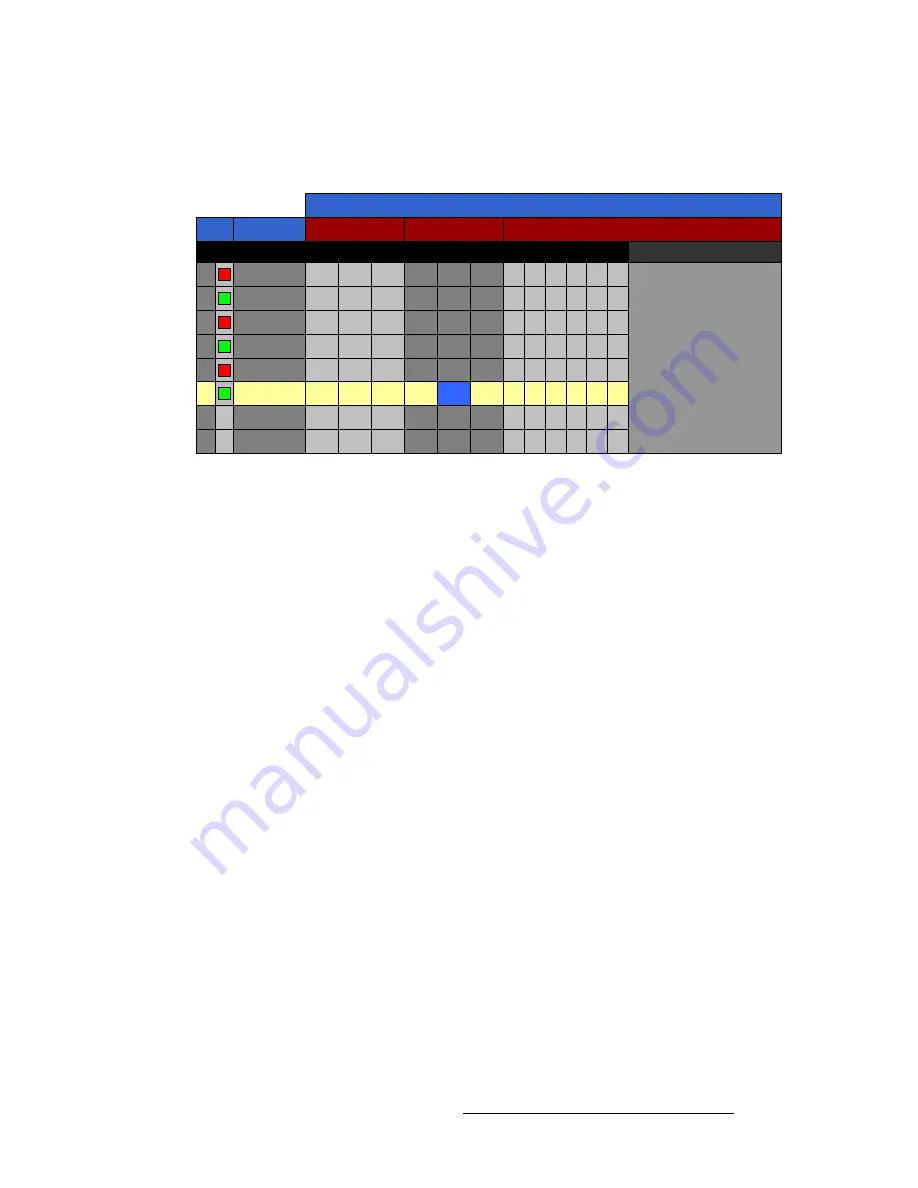
The figure below illustrates a sample
Tally Table
.
Figure 5-103.
Tally table (sample)
The
Tally Table
enables you to associate inputs with tally relays, and set tally closures on
an output-by-output basis. One row is provided for each of the 24 available tallies.
•
The yellow highlight indicates the tally that you want to set up. You can touch any
row to move the highlight, or use the top
Select Tally
knob to scroll vertically.
•
The blue highlight indicates the output for which you want to set (or clear) a relay
closure. You can touch any cell to move the highlight, or use the
Select Output
knob to scroll horizontally. Once an output is selected, press
{Set Tally Closure}
or
{Clear Tally Closure}
as required.
The following columns of information are provided:
•
Tally
— two columns are provided for tally:
~
The left-hand column indicates the selected relay (
1
through
24
).
~
The right-hand column is simply an indication of the type of tally you wish
to set: red, green or amber. Use the
{Select Color}
button to select the
desired color.
•
Input
— indicates the input that you wish to associate with the highlighted tally.
Use the
{Select Input}
button to select the desired input, or the
{Clear Input}
button to remove the input from the table.
•
PGM
— columns are provided for all Program outputs on the
M/E Card
. If a
column heading is grayed out, that output is not available.
•
PST
— columns are provided for all Preview outputs on the
M/E Card
. If a
column heading is grayed out, that output is not available.
•
Installed Aux Outputs
— columns are provided for all installed Auxiliary outputs
on the
M/E Card
, and on the optional
UOC
and
NAC
cards. If the associated
optional cards are not installed, those column headings do not appear.
PGM
ME1
Outputs
PGM
ME2
PST
Installed Aux Outputs
2
1
3
5
4
6
Input
Tally
ME1
PGM
ME2
1
x
CAM1
x
x
2
CAM1
x
x
3
x
CAM2
x
x
4
CAM2
x
x
5
x
CAM3
x
x
6
CAM3
x
x
7
8


